Specific Process Knowledge/Lithography/UVExposure: Difference between revisions
| Line 290: | Line 290: | ||
Equipment info in [http://labmanager.danchip.dtu.dk/function.php?module=Machine&view=view&mach=201 LabManager] | Equipment info in [http://labmanager.danchip.dtu.dk/function.php?module=Machine&view=view&mach=201 LabManager] | ||
===Process information=== | |||
'''Positive tone resists:''' | |||
'''AZ 5214E and AZ 4562''' | |||
Compared to exposure on KS-Aligner, the dose on Aligner-6inch is halved. | |||
*1.5µm: 24.5 mJ/cm<sup>2</sup> corresponding to 3.5 seconds exposure at 7 mW/cm<sup>2</sup>. | |||
*10µm: ~140 mJ/cm<sup>2</sup> corresponding to ~20 seconds exposure at 7 mW/cm<sup>2</sup>. | |||
'''AZ MiR 701''' ''Preliminary results'' | |||
Compared to exposure on KS-Aligner, the dose on Aligner-6inch is one fifth. | |||
*1.5µm: 31.5 mJ/cm<sup>2</sup> corresponding to 4.5 seconds exposure at 7 mW/cm<sup>2</sup>. | |||
'''Negative tone resists''' | |||
'''AZ 5214E image reversal''' | |||
Compared to exposure on KS-Aligner, the dose on Aligner-6inch is halved. | |||
*1.5µm: 10.5 mJ/cm<sup>2</sup> corresponding to 1.5 seconds exposure at 7 mW/cm<sup>2</sup>. | |||
*2.2µm: 12 mJ/cm<sup>2</sup> corresponding to 1.7 seconds exposure at 7 mW/cm<sup>2</sup>. | |||
'''AZ nLOF 20XX''' ''Preliminary results'' | |||
Compared to exposure on KS-Aligner, the dose on Aligner-6inch is the same. | |||
*1.5µm: 42 mJ/cm<sup>2</sup> corresponding to 6 seconds exposure at 7 mW/cm<sup>2</sup>. | |||
*2µm: 49 mJ/cm<sup>2</sup> corresponding to 7 seconds exposure at 7 mW/cm<sup>2</sup>. | |||
*3µm: 56 mJ/cm<sup>2</sup> corresponding to 8 seconds exposure at 7 mW/cm<sup>2</sup>. | |||
*4.3µm: 70 mJ/cm<sup>2</sup> corresponding to 10 seconds exposure at 7 mW/cm<sup>2</sup>. | |||
<br clear="all" /> | <br clear="all" /> | ||
=== Equipment performance and process related parameters === | === Equipment performance and process related parameters === | ||
{| border="2" cellspacing="0" cellpadding="2" | {| border="2" cellspacing="0" cellpadding="2" | ||
!style="background:silver; color:black;" align="center" width="60"|Purpose | !style="background:silver; color:black;" align="center" width="60"|Purpose | ||
| Line 351: | Line 380: | ||
|- | |- | ||
|} | |} | ||
<br clear="all" /> | <br clear="all" /> | ||
Revision as of 09:56, 26 March 2014
Feedback to this page: click here
UV Exposure Comparison Table
| Equipment | KS Aligner | Aligner-6inch | III-V Aligner | Inclined UV Lamp | |
|---|---|---|---|---|---|
| Purpose |
|
|
|
| |
| Performance | Minimum feature size |
|
|
|
|
| Exposure light/filters/spectrum |
|
|
|
| |
| Exposure mode |
|
|
|
| |
| Process parameter range | Positive Process |
|
|
|
|
| Negative Process |
then 210mW/cm2 flood exposure after PEB |
then 210mW/cm2 flood exposure after PEB |
|
| |
| Substrates | Batch size |
|
|
|
|
| Allowed materials |
|
|
|
| |
Mask for UV exposure
When you do UV exposure you need to have a mask. Here you can find information how to design and order your mask.
Tips and tricks for mask designing
Find a guide for L-edit and mask design here:
Unfortunately they are quite old, but may be useful anyway. Note some links/e-mails etc. are not correct anymore
Alignment marks
Following alignment marks are suggested to use on the EVG620 automatic aligner for good pattern recognition. Pleased be adviced that they can be removed in KOH etching.
- Alignment marks 2 .cif - You need the program "Clewin" to open this file
- Alignment marks 2 .tdb - You need the program "L-Edit" to open this file
External links
Alignment marks location
- KS Aligner MA6
- Aligner 6inch EVG620
The mask's alignment marks for 4inch process:
BSA must be located between -1,0 and +1,0 mm in vertical location from mask center (y=0-+1mm) and exactly at 45mm in left and right in horizontal location (x=+-45mm).
TSA must be located 35-45 mm in left and right in horizontal location and between -2 and +2 mm in vertical location.
The mask's alignment marks for 6inch process:
Both BSA and TSA must be located between -2,5 and +2,5 mm in vertical location from mask center and 60 mm in left and right in horizontal location.
Please notice that if you plan to use the automatic alignment option the alignment marks must be displaced from y=0 to y=+/- 1,6mm.
How to order a mask
Our standard mask supplier is Delta Mask. The smallest feature size obtainable from Delta Mask is 1.5 µm. If you need structures smaller than this please write it specificly in the e-mail. Be aware that this will increase the price by at least a factor of 3.
Send your *.cif file or *.gds file (for 7" mask or masks with CD under 1.5µm only *.gds should be used) in an e-mail along with a text file describing your specs (example spec file). E-mail address can be found in Danchip_contact_information. Cost according to Danchip price list.
KS Aligner

Feedback to this section: click here
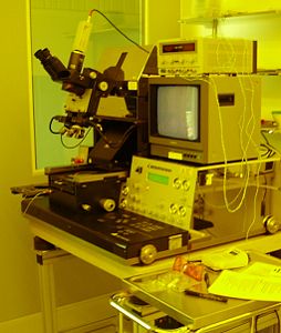
SUSS Mask Aligner MA6 is designed for high resolution photolithography. The 365nm exposure wavelength version is capable of 1.25 (1.0) um resolution in vacuum contact. All contact exposure programs (vacuum, hard, soft, proximity) are supplied. Two alignment options are available: top side alignment (TSA) with a split field or a video microscope and back side alignment (BSA) with BSA microscope. It is also possible to make IR- light alignment.
The user manual(s), quality control procedure(s) and results and contact information can be found in LabManager: Equipment info in LabManager
Process information
Positive tone resists:
AZ 5214E and AZ 4562
Compared to exposure on Aligner-6inch, the dose on KS-Aligner is doubled.
- 1.5µm: 35-49 mJ/cm2 corresponding to 5-7 seconds exposure at 7 mW/cm2.
- 2.2µm: 56-70 mJ/cm2 corresponding to 8-10 seconds exposure at 7 mW/cm2.
- 4.2µm: ~140 mJ/cm2 corresponding to ~20 seconds exposure at 7 mW/cm2.
- 10µm: ~280 mJ/cm2 corresponding to ~40 seconds exposure at 7 mW/cm2.
AZ MiR 701 Preliminary results
Compared to exposure on Aligner-6inch, the dose on KS-Aligner is five-doubled.
- 1.5µm: 157.5 mJ/cm2 corresponding to 22.5 seconds exposure at 7 mW/cm2.
Negative tone resists
AZ 5214E image reversal
Compared to exposure on Aligner-6inch, the dose on KS-Aligner is doubled.
- 1.5µm: 21 mJ/cm2 corresponding to 3 seconds exposure at 7 mW/cm2.
- 2.2µm: 24 mJ/cm2 corresponding to 1.7 seconds exposure at 7 mW/cm2.
AZ nLOF 20XX Preliminary results
Compared to exposure on Aligner-6inch, the dose on KS-Aligner is the same.
- 1.5µm: 42 mJ/cm2 corresponding to 6 seconds exposure at 7 mW/cm2.
- 2µm: 49 mJ/cm2 corresponding to 7 seconds exposure at 7 mW/cm2.
- 3µm: 56 mJ/cm2 corresponding to 8 seconds exposure at 7 mW/cm2.
- 4.3µm: 70 mJ/cm2 corresponding to 10 seconds exposure at 7 mW/cm2.
| Purpose |
Alignment and UV exposure | ||
|---|---|---|---|
| Performance | Exposure mode |
soft contact, hard contact, proximity, flood exposure | |
| Exposure light/filters |
| ||
| Minimum structure size |
down to 1µm | ||
| Mask size |
| ||
| Alignment modes |
| ||
| Substrates | Substrate size |
| |
| Allowed materials |
| ||
| Batch |
1 | ||
Aligner-6inch
Feedback to this section: click here

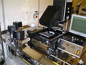
Aligner-6inch, EVG620 aligner, is designed for high resolution photolithography. The machine can be used for 2, 4 and 6 inch substrates. Cassette-to-cassette handling option is available only for 6inch substrates. The automatic pattern recognition software is available for the special alignment marks design recommended of EVGroup. Please contact Danchip staff for further information. Available exposure mode: proximity, soft, hard and vacuum contact. Two alignment options are available: top side alignment (TSA) and back side alignment (BSA). IR-light alignment also an option.
The user manual(s), quality control procedure(s) and results and contact information can be found in LabManager: Equipment info in LabManager
Process information
Positive tone resists:
AZ 5214E and AZ 4562
Compared to exposure on KS-Aligner, the dose on Aligner-6inch is halved.
- 1.5µm: 24.5 mJ/cm2 corresponding to 3.5 seconds exposure at 7 mW/cm2.
- 10µm: ~140 mJ/cm2 corresponding to ~20 seconds exposure at 7 mW/cm2.
AZ MiR 701 Preliminary results
Compared to exposure on KS-Aligner, the dose on Aligner-6inch is one fifth.
- 1.5µm: 31.5 mJ/cm2 corresponding to 4.5 seconds exposure at 7 mW/cm2.
Negative tone resists
AZ 5214E image reversal
Compared to exposure on KS-Aligner, the dose on Aligner-6inch is halved.
- 1.5µm: 10.5 mJ/cm2 corresponding to 1.5 seconds exposure at 7 mW/cm2.
- 2.2µm: 12 mJ/cm2 corresponding to 1.7 seconds exposure at 7 mW/cm2.
AZ nLOF 20XX Preliminary results
Compared to exposure on KS-Aligner, the dose on Aligner-6inch is the same.
- 1.5µm: 42 mJ/cm2 corresponding to 6 seconds exposure at 7 mW/cm2.
- 2µm: 49 mJ/cm2 corresponding to 7 seconds exposure at 7 mW/cm2.
- 3µm: 56 mJ/cm2 corresponding to 8 seconds exposure at 7 mW/cm2.
- 4.3µm: 70 mJ/cm2 corresponding to 10 seconds exposure at 7 mW/cm2.
| Purpose |
Alignment and UV exposure | ||
|---|---|---|---|
| Performance | Exposure mode |
| |
| Exposure light/filters |
| ||
| Minimum structure size |
| ||
| Mask size |
| ||
| Alignment modes |
| ||
| Substrates | Substrate size |
| |
| Allowed materials |
All cleanroom materials except III-V materials | ||
| Batch |
| ||
III-V Aligner
Feedback to this section: click here
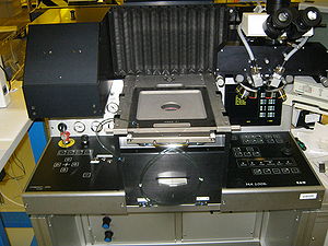
The SÜSS MicroTec MA1006 mask aligner located in the III-V cleanroom is dedicated for processing of III-V compound semiconductors.
Specific use of the mask aligner can be found in the standard resist recipes.

The user manual and contact information can be found in LabManager: Equipment info in LabManager
| Purpose |
Alignment and UV exposure | ||
|---|---|---|---|
| Performance | Exposure mode |
soft contact, hard contact, proximity, flood exposure | |
| Exposure light/filters |
365 nm, 405 nm | ||
| Minimum structure size |
down to 2µm | ||
| Mask size |
5x5inch | ||
| Alignment modes |
Top side only | ||
| Substrates | Substrate size |
| |
| Allowed materials |
III-V materials | ||
| Batch |
1 | ||
Inclined UV Lamp
Feedback to this section: click here

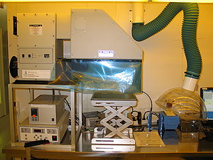
The Inclined UV lamp is 1000 W Hg(Xe)lamp source designed for near UV, 350-450nm, mid UV, 260-320nm, and deep UV, 220-260nm exposures of resists and polymers. The exposure source can be also used to make an inclined exposure in air or in the media tank.
The tool was purchased in February 2009 from Newport. The exposure lamp has a official name: Oriel Flood Exposure Source, unit 92540. All other parts of equipment: substrate and mask holder with media tank, exhaust box around the tool, timer controller, were designed and build at DTU Danchip workshop.
The substrate and mask holder with a media tank was designed as part of Master Thesis of DTU Nanotech, Andres Kristensen group. The exhaust box was made as part of safety and the timer controller was build to control exposure time.
The technical specification and the general outline of the equipment can be found in LabManager.
The user manual(s), quality control procedure(s) and results and contact information can be found in LabManager: Equipment info in LabManager
| Purpose |
UV exposure | ||
|---|---|---|---|
| Performance | Exposure mode |
| |
| Exposure light/filters |
| ||
| Minimum structure size | |||
| Mask size |
5x5inch optinal | ||
| Alignment modes |
No alignment possible | ||
| Substrates | Substrate size |
Up to 8inch substrates, different shapes | |
| Allowed materials |
All cleanroom materials | ||
| Batch |
1 | ||
