Specific Process Knowledge/Lithography/LiftOff
The contents on this page, including all images and pictures, was created by DTU Nanolab staff unless otherwise stated.
Feedback to this page: click here
Lift-off Comparison Table
| Equipment | Lift-off | Fume hood 03: Solvents - requires login | |
|---|---|---|---|
| Purpose |
Lift-off of e.g. metal using
|
General solvent work, including lift-off. DO NOT use other fume hoods for lift-off!
| |
| Bath chemical |
NMP (Remover 1165) / Rinse in IPA |
User defined | |
| Process parameters | Process temperature |
|
Heating is possible using portable hotplate or portable ultrasonic bath |
| Ultrasonic agitation |
|
Ultrasonic agitation is possible using portable ultrasonic bath | |
| Substrates | Substrate size |
|
|
| Allowed materials |
|
Any cleanroom material | |
| Batch |
1 - 25 |
1 | |
Lift-off process
The lift-off process is used to pattern a material that can be deposited as a film on a substrate. The material is patterned by depositing the film on top of a patterned masking material, which is then dissolved, thus leaving only parts of the substrate covered in the material. Although this may in theory be done using any combination of mask and material, the most common is using photoresist as a lift-off mask for metal.
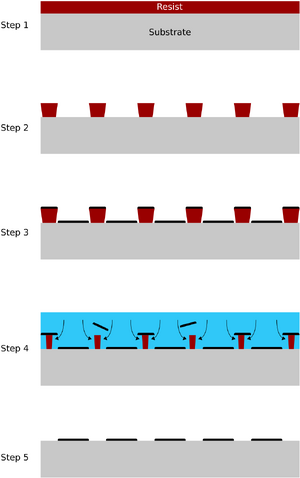
The image to the left shows a schematic of the lift off process.
- The substrate is coated with the masking material
- The masking material is patterned. The mask must be a negative image of the desired material pattern
- The material is deposited on top of both mask and substrate. The mask sidewall slope should be negative in order to prevent the material covering the sidewalls during deposition
- The masking material is dissolved, thus lifting part of the deposited material
- The remaining material forms the desired pattern on the substrate
A successful lift-off process is dependent on many factors, including:
- Resist sidewall angle
- Resist thickness relative to the deposited material
- Layout of the design, especially the regions surrounding the device(s)
If the resist sidewall angle is positive, the deposited material will coat the sidewall, thus preventing the solvent from reaching and dissolving the resist. Ultrasonic agitation may be able to pierce the material deposited on top of resist, allowing lift-off. A a positive sidewall angle will typically result in a very slow lift-off process, as well as line edge roughness of the deposited material. A negative, or at least vertical, resist sidewall is usually needed for a successful lift-off process.
If the resist layer used for lift-off is too thin compared to the deposited layer, solvent access to the resist may be limited, due to partial or full coverage of the sidewalls. This would result in a slow lift-off, possibly with line edge roughness of the deposited material. As a rule of thumb, the resist should be 5-10 times thicker than the deposited material.
Small, tightly packed structures result in a very fast lift-off process. It is usually the big, uncovered areas between or around the device(s) that limit the lift-off speed. The less of the deposited material is to remain on the substrate after lift-off, the longer the sample has to spend in the lift-off solvent while resist under the deposited material is being dissolved and transported out. During the design of the pattern used for lift-off, it should be considered to fill any voids between devices with lift-off assisting dummy structures (e.g. hatching or squares/circles), in order to punctuate the open spaces, and allow for multiple, parallel starting points. Consider also if the edge of the substrate (exclusion zone) could be left covered with the deposited material.
Please note:
At the DTU Nanolab cleanroom facility, it is only allowed to do lift-off in:
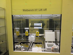
- Lift-off (Wet bench 07)
- Fume hood 03: Solvents - requires login
Other fume hoods, such as Fume hood 04: Solvents, Fume hood 09: UV development, and Fume hood 10: e-beam development, should not be used for lift-off. For an overview of the fume hoods, click here.
Lift-off at Nanolab
Lift-off wet bench 07
The user manual, and contact information can be found in LabManager - requires login
| Equipment | Lift-off | |
|---|---|---|
| Purpose |
| |
| Bath chemical |
| |
| Process parameters | Process temperature |
Heating of the bath is possible. The heating has been limited to 65°C |
| Ultrasonic agitation |
Continuous or pulsed The power may be varied | |
| Substrates | Substrate size |
|
| Allowed materials |
Silicon or glass wafers Film or patterning of all but Type IV (Pb, Te) | |
| Batch |
1 - 25 | |
Process information
Lift-off is used for lift-off using resists that are soluble in NMP (N-Methyl-Pyrrolidone), supplied in the cleanroom as "Remover 1165". Both AZ 5214E and AZ nLOF are soluble in NMP.
For information on processing of AZ nLOF, or image reversal of AZ 5214E, see here: Resist Overview.

