Specific Process Knowledge/Lithography/Coaters/Spin Coater: RCD8 processing
This section, including all images and pictures, is created by DTU Nanolab staff unless otherwise stated.
Feedback to this page: click here
Spin coating
Spin coating on Spin Coater: RCD8 consists of a selection of the following steps:
- Optional: Acceleration to a low spin speed if dynamic dispense is used
- Resist dispense
- Optional: Closing the Gyrset (if used)
- Optional: Resist spreading at low spin speed
- Spin-off
- Deceleration
- Opening Gyrset
The wafer is first centered on the chuck and held in place by vacuum (or pins in the case of the non-vacuum chuck). If static dispense is used, the spindle remains static during the ensuing resist dispense. In the case of dynamic dispense, the spindle is accelerated to a low spin speed before the resist is dispensed. Using too high spin speed during dispense can cause surface wetting issues, while a too low spin speed causes the resist to flow onto the backside of the wafer. The resist may be dispensed manually, or automatically using the syringe dispense system on the media arm. After dispense, a short spin at low spin speed may be used in order to spread the resist over the wafer surface before spin-off.
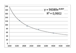
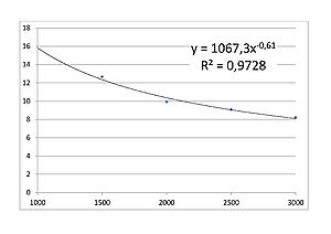
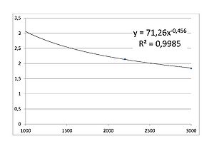
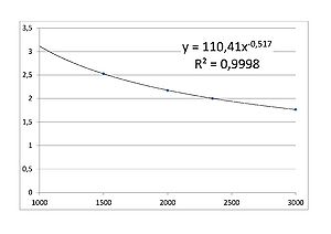
The spin-off cycle determines the thickness of the resist coating. The thickness is primarily a function of the spin-off speed and the spin-off time, both following an inverse power-law. The acceleration to the spin-off speed also influences the thickness, but the effect is dependent on previous steps. The spin-off is usually a simple spin at one speed, but it may be comprised of several steps at different spin speeds. After spin-off, the wafer is decelerated.
Automatic dispense
Automatic dispense on the Spin Coater: RCD8 is done using a Nordson EFD Performus VII pressurised cartridge dispense system. The syringe containing the resist is mounted on the media arm, and the resist is dispensed using a nitrogen pressure supplied by the control box. The dispense rate is controlled by the nitrogen pressure, while the dispense time, and thus the volume, is set in the recipe. The dispensed volume may be estimated by measuring the distance the resist level is displaced during a dispense, and calculating the corresponding volume using the diameter of the syringe (23 mm). A displacement of 10 mm corresponds to a dispensed volume of 4 mL.
Observed dispense rates (uncertainty from measurements ~0.1 ml/s):
- SU-8 2075:
- 0.2 ml/s @ 1.0 bar
- 0.5 ml/s @ 2.0 bar
- 0.7 ml/s @ 3.0 bar
- SU-8 2035:
- 0.5 ml/s @ 1.0 bar
- SU-8 2010:
- 1.1 ml/s @ 0.1 bar
- KMPR 1025:
- 0.4 ml/s @ 0.5 bar
- 0.7 ml/s @ 1.0 bar
- AZ 5214E:
- 1.2 ml/s @ 0.1 bar
- 2.4 ml/s @ 0.18 bar
Edge bead removal
The automatic dispense system may also be used to administer solvent at the edge of the wafer after spin coating in order to remove the edge bead. Edge bead removal, or EBR, is usually done using PGMEA. Due to the low viscosity of the solvent, and the relatively high pressure of the EFD control box, it is necessary to use at tip at the end of the syringe. The flow rate of the solvent is a function of the pressure and the size of the tip orifice. While the dispense rate scales roughly linearly with the pressure, it is an exponential function of the tip orifice.
Observed dispense rates of PGMEA (uncertainty from measurements ~0.1 ml/s) for different tip sizes:
- Red (0.010"):
- 0.2 ml/s @ 0.1 bar
- 0.25 ml/s @ 0.2 bar
- Purple (0.020"):
- 0.3 ml/s @ 0.1 bar
- 0.65 ml/s @ 0.2 bar
- Pink (0.024"):
- 0.5? ml/s @ 0.1 bar (not verified)
- Grey (0.047"):
- ~2.5 ml/s @ 0.1 bar
Recipes
Auxiliary recipes, and template recipes. For each case a list of the steps/parameters in the respective recipe.
Process recipes developed by Nanolab are listed under Process results.
Auxiliary recipes
- 1 DCH Centering test
5s @ 100rpm; 5s @ 250rpm; 5s @ 500rpm.
- 1 DCH Chuck cleaning
10s @ 100rpm; 1s @ 0rpm; 10s @ -30rpm; 20s @ 1500rpm.
- 1 DCH Gyrset cleaning
Gyrset down; 10s @ 100rpm; 1s @ 0rpm; 10s @ -30rpm; 20s @ 1500rpm; Gyrset up.
- 1 DCH predispense
0.2s dispense at cup (arm position 0mm).
Manual dispense templates
- 1 TMPLT man disp
Spin-off; deceleration.
- 1 TMPLT man disp spread
Spread step; spin-off; deceleration.
- 1 TMPLT man disp Gyrset
Gyrset down; spin-off; deceleration; Gyrset up.
- 1 TMPLT man disp Gyrset sprd
Gyrset down; spread step; spin-off; deceleration; Gyrset up.
Automatic dispense templates
- 1 TMPLT aut disp SU8
Dispense; SU-8 string breaking; spread step; spin-off; deceleration.
- 1 TMPLT aut disp SU8 Gyrset
Dispense; SU-8 string breaking; Gyrset down; spread step; spin-off; deceleration; Gyrset up.
- 1 TMPLT aut disp
Dispense; spin-off; deceleration.
- 1 TMPLT aut disp spread
Dispense; spread step; spin-off; deceleration.
- 1 TMPLT aut disp Gyrset
Dispense; Gyrset down; spin-off; deceleration; Gyrset up.
- 1 TMPLT aut disp Gyrset sprd
Dispense; Gyrset down; spread step; spin-off; deceleration; Gyrset up.
Processing results
SU-8 2075
Spin coating of SU-8 2075 on Spin Coater: RCD8 using automatic dispense consists of three process steps: static dispense, spread, and spin-off. In the static dispense step the media arm is moved to the center of the wafer, and resist is dispensed for 7s, yielding a volume of 3.5ml at 2.0 bar. After the dispense, the media arm is moved up and down in a series of steps designed to break the string of resist between the syringe and the wafer. In the spread step the wafer is accelerated to 700rpm at 50rpm/s, and spun for 25s. In the spin-off step the wafer is accelerated at 500rpm/s to the spin-off speed, spun for 30s, then decelerated at 1000rpm/s.
In the Gyrset version, the Gyrset is closed after the dispense step, and opened after the spin-off step.
Recipe names, process parameters, and test results:
- 1 DCH SU8 aut disp 100um
Spin-off: 30 s at 2100 rpm.
| Substrate | Thickness | Uniformity (+/-) | Test date | Tester initials | Comments |
|---|---|---|---|---|---|
| Silicon with native oxide | 100 µm | 3.5% | 14/4 2015 | taran | 5 points on one wafer, exclusion zone 15mm |
- 1 DCH SU8 aut dsp Grst 100um
Spin-off: 30 s at 2000 rpm.
| Substrate | Thickness | Uniformity (+/-) | Test date | Tester initials | Comments |
|---|---|---|---|---|---|
| Silicon with native oxide | 99 µm | 3.0% | 15/4 2013 | taran | 5 points on one wafer, exclusion zone 15mm |
AZ 4562
Spin coating of AZ 4562 on Spin Coater: RCD8 using manual dispense is a very simple process. The wafer is accelerated at 1000rpm/s to the spin-off speed, spun for 30s, then decelerated at 1000rpm/s.
Recipe names, process parameters, and test results:
- 1 DCH 4562 man disp 10um
Spin-off: 30 s at 2000 rpm.
| Substrate | Thickness | Uniformity (+/-) | Test date | Tester initials | Comments |
|---|---|---|---|---|---|
| Silicon with native oxide | 9.92 µm | 2.9% | 29/4 2015 | taran | 9 points on one wafer, exclusion zone 5mm Non-vacuum chuck |
AZ 5214E
Spin coating of AZ 5214E on Spin Coater: RCD8 using manual dispense is a very simple process. The wafer is accelerated at 1000rpm/s to the spin-off speed, spun for 30s, then decelerated at 1000rpm/s.
Recipe names, process parameters, and test results:
- 1 DCH 5214E man disp 2.2um
Spin-off: 30 s at 2100 rpm.
| Substrate | Thickness | Uniformity (+/-) | Test date | Tester initials | Comments |
|---|---|---|---|---|---|
| Silicon with native oxide | 2.19 µm | 0.4% | 22/4 2013 | taran | 9 points on one wafer, exclusion zone 5mm |
AZ MiR 701
Spin coating of AZ MiR 701 (29cps) on Spin Coater: RCD8 using manual dispense is a very simple process. The wafer is accelerated at 1000rpm/s to the spin-off speed, spun for 30s, then decelerated at 1000rpm/s.
Recipe names, process parameters, and test results:
- 1 DCH MiR 701 man disp 2um 1)
Spin-off: 30 s at 2350 rpm.
| Substrate | Thickness | Uniformity (+/-) | Test date | Tester initials | Comments |
|---|---|---|---|---|---|
| Silicon with native oxide | 2.00 µm | 1.8% | 29/4 2015 | taran | 9 points on one wafer, exclusion zone 5mm Non-vacuum chuck |
1) Not implemented yet.
AZ nLOF 2020
Spin coating of AZ nLOF 2020 on Spin Coater: RCD8 using manual dispense is a very simple process. The wafer is accelerated at 1000rpm/s to the spin-off speed, spun for 30s, then decelerated at 1000rpm/s.
Recipe names, process parameters, and test results:
- 1 DCH nLOF 2020 man disp 2.3um 1)
Spin-off: 30 s at 2500 rpm.
| Substrate | Thickness | Uniformity (+/-) | Test date | Tester initials | Comments |
|---|---|---|---|---|---|
| Silicon with native oxide | 2.30 µm | 1.7% | 29/4-2015 | taran | 9 points on one wafer, exclusion zone 5mm Non-vacuum chuck |
1) Not implemented yet.


