Specific Process Knowledge/Lithography/Strip/plasmaAsher04 processDevelopment
Process gas ratio for plasma asher 4 & 5

The ashing rate is related to the gas mix, usually expressed as percentage of nitrogen of the total amount of gas. Process development tests found that a gas mix of 50% nitrogen gives the highest ashing rate for both processing single substrates and when processing a full boat with 25 substrates.
Please note that the ashing rate for a full boat is approximately ten times slower, than the processing time for a single substrate.
| Single substrate | Full boat | |
|---|---|---|
| Test results | Highest ashing rate at 30-80% Nitrogen | Highest ashing rate at 50-70% Nitrogen |
| Wafers | 1 | 25 |
| Wafer size | 100 mm | 100 mm |
| Boat position | Center of chamber | Center of chamber |
| Test wafer position | Center of boat | Center of boat |
| Total gas flow rate | 500 sccm | 200 sccm |
| Gas mix ratio | Tested parameter | Tested parameter |
| Chamber pressure | 1.25 mbar | 1.3 mbar |
| Power | 1000 W | 1000 W |
| Test processing time | 2 minutes | 10 minutes |
| Test average temperature | 43°C | 47°C |
Process chamber pressure for plasma asher 4 & 5

The ashing rate is related to the chamber pressure during processing. Process development tests found that 1.3 mbar gives the highest ashing rate for both processing single substrates and when processing a full boat with 25 substrates.
Please note that the ashing rate for a full boat is approximately ten times slower, than the processing time for a single substrate.
| Single substrate | Full boat | |
|---|---|---|
| Test results | Highest ashing rate at 1.3 mbar | Highest ashing rate at 1.4 mbar |
| Wafers | 1 | 25 |
| Wafer size | 100 mm | 100 mm |
| Boat position | Center of chamber | Center of chamber |
| Test wafer position | Center of boat | Center of boat |
| Total gas flow rate | 150 sccm | 200 sccm |
| Gas mix ratio | 30% N2 | 50% N2 |
| Chamber pressure | Tested parameter | Tested parameter |
| Power | 1000 W | 1000 W |
| Test processing time | 2 minutes | 10 minutes |
| Test average temperature | 43°C | 55°C |
Process gas flow rate for plasma asher 4 & 5

The ashing rate is related to the total gas flow rate during processing. Process development tests found that 200 sccm gives the highest ashing rate for both processing single substrates and when processing a full boat with 25 substrates. The experiments indicate that the gas flow rate has only a minor impact on the ashing rate.
Please note that the ashing rate for a full boat is approximately ten times slower, than the processing time for a single substrate.
| Single substrate | Full boat | |
|---|---|---|
| Test results | Highest ashing rate at 200 sccm | Highest ashing rate at 200 sccm |
| Wafers | 1 | 25 |
| Wafer size | 100 mm | 100 mm |
| Boat position | Center of chamber | Center of chamber |
| Test wafer position | Center of boat | Center of boat |
| Total gas flow rate | Tested parameter | Tested parameter |
| Gas mix ratio | 30% N2 | 30% N2 |
| Chamber pressure | 1.3 mbar | 1.3 mbar |
| Power | 1000 W | 1000 W |
| Test processing time | 2 minutes | 10 minutes |
| Test average temperature | 43°C | 47°C |
Process power for plasma asher 4 & 5

The ashing rate is related to the power used during processing. Higher power increases ashing rate.
| Single substrate | |
|---|---|
| Test results | Ashing rate follows Power |
| Wafers | 1 |
| Wafer size | 100 mm |
| Boat position | Center of chamber |
| Test wafer position | Center of boat |
| Total gas flow rate | 200 sccm |
| Gas mix ratio | 30% N2 |
| Chamber pressure | 1.3 mbar |
| Power | Tested parameter |
| Test processing time | 2 minutes |
| Test average temperature | 40°C |
Process temperature for plasma asher 4 & 5

The ashing rate is related to the temperature during processing. Higher temperature increases ashing rate.
| Single substrate | |
|---|---|
| Test results | Ashing rate follows temperature |
| Wafers | 1 |
| Wafer size | 100 mm |
| Boat position | Center of chamber |
| Test wafer position | Center of boat |
| Total gas flow rate | 200 sccm |
| Gas mix ratio | 30% N2 |
| Chamber pressure | 1.3 mbar |
| Power | 1000 W |
| Test processing time | 2 minutes |
| Test average temperature | Tested parameter |
Comparison of ashing rate between substrate sizes for plasma asher 4 & 5

The ashing rate is highest for 100 mm substrates, lower for 150 mm substrates and even lower for 200 mm substrates.
All substrate sizes follows the same pattern:
- Ashing rate increases with a higher percentage nitrogen in the gas mix
- Ashing rate increases with a higher chamber pressure
- The total gas flow has only little influence on the ashing rate, but slightly favors the lower flow rate of 200 sccm, similar to previous experiment results
Process parameter impact on ashing rate
Investigating the ashing rate using linear regression models on the process parameters, indicates that the gas mix and the chamber pressure has a significant impact on the ashing rate, while the gas flow has only little effect:
-
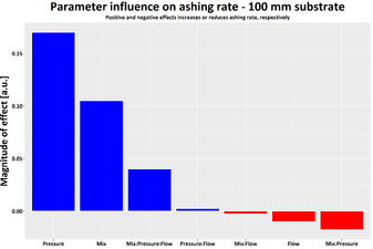 100 mm parameter impact
 -
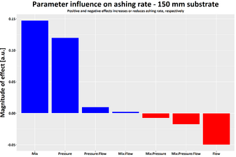 150 mm parameter impact
 -
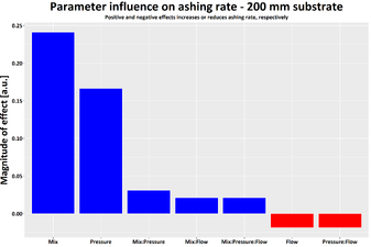 200 mm parameter impact


