Specific Process Knowledge/Etch/KOH Etch/ProcessInfo
QC
Quality Control (QC) for the KOH Si etching baths.
| Quality Control (QC) for Si Etch 01, and Si Etch 02 | ||||||||||||||||||||||||||
|
Mixing KOH
Danchips standard solution in the KOH baths has a concentration of 28 wt% and is mixed of either 500 g KOH pills to 1 l of water or 1liter of a premade 50wt% KOH solution to 1.2 l of water.
If you want to make your own mixture of KOH in a beaker in Fumehood 6 you can either do this by using KOH pills or a premade mixture of 50wt%. Using the pills the mixture will spontaneously heat up when mixing which is not the case when using the premade mixture.
If you want to make solution using the KOH pills you must remember that the pills are only 85% pure.
For 1 l of water you can calculate the required amount of KOH pills (X) to achieve the desired concentration in wt% (Y) by:
(0.85 ∙X)/(X+1000g)=Y
X=(Y∙1000g)/(0.85-Y)
So for a 10wt% solution you will need 133 g pills for each liter of water.
If you use the 50wt% premade solution you can calculate the amount of solution X you need to add 1 liter of water to achieve a concentration of Y wt% by:
(0.5∙1.509 g/ml ∙X)/(X∙1.509 g/ml+1000g)=Y
X=(Y∙1000g)/(1.509 g/ml∙(0.5-Y))
where 1.509 g/ml is the density of a 50wt% solution KOH at 20 °C.
So for a 10 wt% solution you will need 165 ml of KOH to 1 l of water.
Theory
Definition of structures
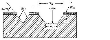
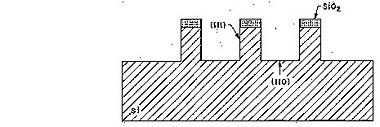
Due to the almost inert (111)-planes it is possible by KOH etching to realize high aspect ratio structures in sigle crytalline silicon using the (111)-planes as sidewalls. In Si(100) these sidewalls are inclined - 54.7o with respect to the (100) surface - whereas in Si(110) the sidewalls are vertical (see figures below).
- Anisotropic wet silicon etch: dependency on crystal orientation
-
Etched profile when etching Si(100).
-
Etched profile when etching Si(110).
For Si(100), the relation between the width of the bottom of the etched groove (Wb) and the width of the opening (Wo) at the wafer surface in a groove etched to the depth l is given by:
Definition of <110> alignment structures
The etch rate dependence on the crystallographic planes can be used to determine the <110> crystal directions with high precision (better than +/- 0.05 o). A fast method for doing this, using the symmetric under-etching behavior around but not at the <110>-directions, was described by Vangbo and Bäcklund in J. Micromech. Microeng.6 (1996), 279-284. High-precision control of the <110>-direction during alignment can be necessary in order to control the dimensions of KOH-etched structures (e.g. precise control of V-groove dimensions). A dedicated mask (MASK NAME) has been designed for this purpose.
Etch rates: Empirical formula (Seidl et al)
The following empirical formula can be used for concentrations in the range of 10-60 wt%:
R = k0 [H2O]4 [KOH]0.25 e-Ea/kT,
where k0 = 2480 µm/hr (mol/l)-4.25, Ea = 0.595 eV for Si(100)
and k0 = 4500 µm/hr (mol/l)-4.25, Ea = 0.60 eV for Si(110)


