Specific Process Knowledge/Wafer and sample drying/Critical Point Dryer: Difference between revisions
No edit summary |
|||
| Line 17: | Line 17: | ||
!style="background:silver; color:black" align="left" valign="top" rowspan="2"|Process parameter range | !style="background:silver; color:black" align="left" valign="top" rowspan="2"|Process parameter range | ||
|style="background:LightGrey; color:black"|Process Temperature | |style="background:LightGrey; color:black"|Process Temperature | ||
|style="background:WhiteSmoke; color:black"| | |style="background:WhiteSmoke; color:black"|0<sup>o</sup>C to 45<sup>o</sup>C | ||
0< | |||
|- | |- | ||
|style="background:LightGrey; color:black"|Process pressure | |style="background:LightGrey; color:black"|Process pressure | ||
| Line 47: | Line 46: | ||
|- | |- | ||
|} | |} | ||
==Comparison of samples dried in air and with Critical Point Dryer== | ==Comparison of samples dried in air and with Critical Point Dryer== | ||
Revision as of 10:43, 4 December 2012
Critical Point Dryer

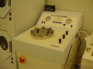
The critical point dryer is used to dry fragile structures that may be damaged in a normal drying procedure. Fragile structures may be thin membranes, or free hanging structures like cantilevers and grippers.
In the critical point dryer, these structures are dried in CO. In the drying process, the sample is first put into Isopropanol, and loaded into the machine. In the process itself, the isopropanol is exchanged for liquid CO. When there is only CO in the machine, the pressure and temperature in the chamber is raised, above the so called “critical point”. In this way, there is never a liquid/gas interface, but instead the liquid is turned into a mixture of equal parts of gas and liquid. Because of this, the problem with surface tension, which destroys the fragile structures through capillary forces, is avoided.
| Purpose | Drying of wafers or chips |
To dry fragile structures (example membranes, grippers, cantilevers). |
|---|---|---|
| Process parameter range | Process Temperature | 0oC to 45oC |
| Process pressure |
1 atm to (maximum) 95 atm (1400 PSI) | |
| Substrates | Batch size |
|
| Substrate material allowed |
| |
| Material allowed on the substrate |
|
Comparison of samples dried in air and with Critical Point Dryer
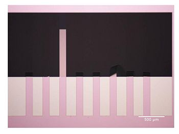
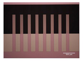
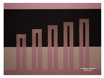
This shows a comparison of samples that have been dried in the critical point dryer, and samples that have been dried in air. Below are pictures of two wafers that have been prepared in the same way- but dried with different methods after the final etching step. Cantilevers of SiN, up to 710 µm long and 100 µm wide, are fabricated in the etching step. The thickness of the cantilevers is about 0.5 µm
After drying wafers in air, the majority of the cantilevers are bended and sticking to the underlying surface. But after the wafers were dried in Critical point dryer, the cantilevers were free hanging.

Dried in air: most cantilevers are bended.

Dried with Critical Point Dryer. The cantilevers are free hanging, and have not bended. The dimensions of the cantilevers are 100 x 710 µm, and the thickness is about 0.5 µm.

Dried with the Critical Point Dryer. The cantilevers structures are free hanging after the drying.
An acknowledgment goes to Tom Larsen, Nanoprobes, DTU Nanotech, who provided the pictures.
