Specific Process Knowledge/Back-end processing/Disco Saw: Difference between revisions
| Line 18: | Line 18: | ||
|- align="center" | |- align="center" | ||
| '''GOOD design''' || '''GOOD design''' || '''BAD design''' | | '''GOOD design''' || '''GOOD design''' || <span style="color:red">'''BAD design'''</span> | ||
|- border="1" align="center" | |- border="1" align="center" | ||
| Line 25: | Line 25: | ||
|- align="center" | |- align="center" | ||
| '''GOOD design''' || '''GOOD design''' || '''BAD design''' | | '''GOOD design''' || '''GOOD design''' || <span style="color:red">'''BAD design'''</span> | ||
|} | |} | ||
Revision as of 16:20, 6 August 2019
Feedback to this page: click here
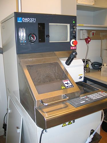
Disco Automatic dicing saw, model DAD321
The dicer feature versatile processing capabilities, compact designs, and high precision and reliability. Users perform workpiece loading, alignment, and unloading manually.
The dicer at DTU Nanolab is placed in room 157 on the first floor in bldg. 346. Please notice that this is not a cleanroom and that the dicing process is very dirty.
In general it is not allowed to bring back your samples into the Cleanroom. You need approval from DTU Nanolab staff to do this. Your samples have to be thoroughly cleaned in the gowning area and get a Piranha cleaning. You will only be allowed to use a limited number of tools for the processing after dicing.
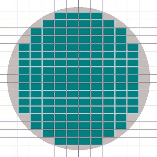
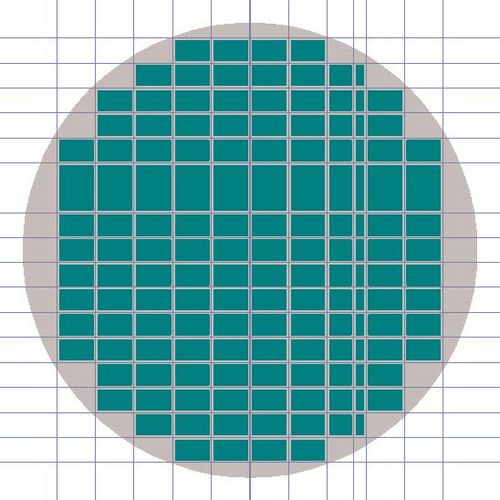
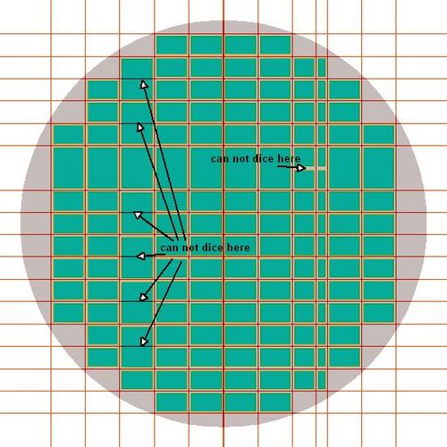
Please consider your layout of dies on your wafer. The dicer can only cut straight lines across the wafer and you can not end a line in the middle of the wafer. Please see the illustrations for a good and a bad design.
| GOOD design | GOOD design | BAD design | |
 |
 |
|
|
| GOOD design | GOOD design | BAD design |
The user manual, user APV, technical information and contact information can be found in LabManager:
Process information
- Comparing dicing parameters for different materials
- Images of diced samples
- Dicing work sheet: Dicing.doc Fill out before requesting dicing.
Overview of the performance Disco DAD321 Dicer
| Purpose | Equipment for dicing out samples |
|
|---|---|---|
| Performance | X-axis cutting range |
192 mm |
| X-axis cut speed |
0.1 - 300 mm/sec | |
| Y-axis cutting range |
162 mm | |
| Y-axis index step |
0.0002 mm | |
| Y-axis single error |
0.003 or less | |
| Hardware settings | Maximum blade size |
ø76.2 mm |
| Substrates | Substrate size |
up to 6" |
| Layers that can't be diced |
|
Comparing dicing parameters for different materials
| Silicon | Pyrex or bonded Si/Pyrex | |
|---|---|---|
| Bladetype | HUB Blade ZH05 (27HEEF) | HUBless Blade B1A862 |
| Blade width | 50 µm | 150 µm |
| Cutlinewidth | 60 µm | 180 - 200 µm |
| Recommended feed speed | Up to 20 mm/sec | Up to 2 mm/sec (0.5 mm/sec) |
| Recommended dice depth | Set blade height to 200µm (preferred). This leaves 125µm uncut since blue tape is 75µm. It is possible to cut through the sample. |
Set blade height to 200µm (preferred). This leaves 125µm uncut since blue tape is 75µm. It is possible to cut through the sample. |
| Max. sample thickness | 1.5 mm | 2.0 mm |
Images of diced samples
