LabAdviser/Technology Research/Organic Ice Resists for Electron-Beam Lithography - Instrumentation and Processes/SEM-LEO Customizations for Organic Ice Resists: Difference between revisions
No edit summary |
mNo edit summary |
||
| Line 21: | Line 21: | ||
==Cryogenics== | ==Cryogenics== | ||
The cryogenic elements represent the main additions to the inner SEM chamber. A large cold finger and a cryostage are connected together by a copper braid, and mounted onto the same vacuum flange on the right side of the SEM | The cryogenic elements represent the main additions to the inner SEM chamber. A large cold finger and a cryostage are connected together by a copper braid, and mounted onto the same vacuum flange on the right side of the SEM. The cold finger is mechanically attached to a copper rod feed-through. The external ambient end of the rod stays suspended into a vacuum flask filled with liquid nitrogen on the SEM table. Two hours after immersing the copper rod in liquid nitrogen, the cold finger and cryostage cool to 110 K and 130 K, respectively. The lowest possible temperature of the cryostage is 120 K. | ||
==Practical Stuff== | |||
The overall vacuum schematics once all systems are in place is displayed in the image. An external rack houses the temperature, gate valve control and interlock, and the load-lock pump controller. The pumping controller is interfaced with the interlock inside the rack and with the load-lock turbo and roughing pumps which are located under the cleanroom floor, and can control both of them individually. | |||
Only the load-lock (and, occasionally, a RGA) are permanently installed since they do not affect the SEM chamber volume nor regular operation. Hence, the first step for OIR lithography is to mount the cryosystems and the GIS, and the last step is to unmount them. Instructions regarding the ice lithography setup assembly, operation and control using the rack interfaces is available through training videos. | |||
'''For information, contact:''' | |||
* [mailto:dizhao@dtu.dk Ding Zhao (PostDoc)] | |||
* [mailto:annaels@dtu.dk Anna Elsukova (PostDoc)] | |||
Revision as of 19:14, 14 June 2018
Feedback to this page: click here
SEM-LEO Customizations for Organic Ice Resists
Overview

The standard EBL setup, consisting in a vacuum chamber, a moving stage for sample navigation and an electron-beam gun for imaging and exposure, is not sufficient by itself to provide the necessary conditions to investigate lithography on ice layers: no chamber inlet is available for injecting gas precursors, and sample holders are evidently at room-temperature.
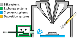
The LEO SEM has been provided with a dedicated load-lock and transfer system. Through removable add-ons, it can cool down and warm up, and image or expose samples under cryogenic conditions. Gas can be prepared in the external apparatus and injected into the chamber, and it is possible to monitor the whole process in terms of temperature, pressure, atmosphere composition, and so on. The SEM is now a functional, self-contained lithography system for ice processing.
Gas Injection System
Loadlock
On the left-hand side of the chamber, the load-lock system was implemented to allow exchange operations without condensation of ambient humidity onto cold parts and samples. Since it avoids main chamber ventilation, such a setup maintains stable high vacuum levels inside the SEM, so it can be also useful for regular room-temperature EBL operation, providing a faster and cleaner exchange.
The load-lock has its own turbo and roughing pump, separated from the SEM ones. The roughing pump runs a parallel line to the GIS and can be isolated and operated independently, to pump and exchange precursors.
Cryogenics
The cryogenic elements represent the main additions to the inner SEM chamber. A large cold finger and a cryostage are connected together by a copper braid, and mounted onto the same vacuum flange on the right side of the SEM. The cold finger is mechanically attached to a copper rod feed-through. The external ambient end of the rod stays suspended into a vacuum flask filled with liquid nitrogen on the SEM table. Two hours after immersing the copper rod in liquid nitrogen, the cold finger and cryostage cool to 110 K and 130 K, respectively. The lowest possible temperature of the cryostage is 120 K.
Practical Stuff
The overall vacuum schematics once all systems are in place is displayed in the image. An external rack houses the temperature, gate valve control and interlock, and the load-lock pump controller. The pumping controller is interfaced with the interlock inside the rack and with the load-lock turbo and roughing pumps which are located under the cleanroom floor, and can control both of them individually.
Only the load-lock (and, occasionally, a RGA) are permanently installed since they do not affect the SEM chamber volume nor regular operation. Hence, the first step for OIR lithography is to mount the cryosystems and the GIS, and the last step is to unmount them. Instructions regarding the ice lithography setup assembly, operation and control using the rack interfaces is available through training videos.
For information, contact:
