Specific Process Knowledge/Lithography/EBeamLithography/BEAMER: Difference between revisions
| Line 154: | Line 154: | ||
|[[File:beamer6.jpg|400px|right]] | |[[File:beamer6.jpg|400px|right]] | ||
|- align="center" | |- align="center" | ||
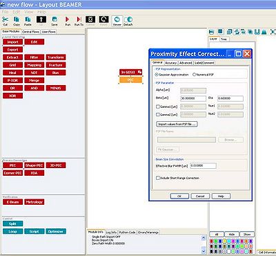
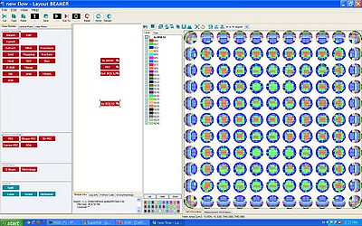
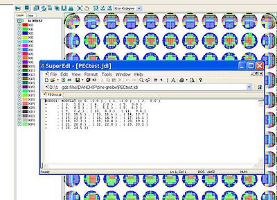
| Add a PEC-module on top of the import module. A Proximity Error Correction parameter window opens.|| | | Add a PEC-module on top of the import module. A Proximity Error Correction parameter window opens. Here, you can either type in values of alpha, beta and eta or load a point spread function.|| After converting to v30-format, the dose variation is illustrated in your pattern || BEAMER has at this point created a jdi-file in the same folder as the v30-file. This jdi-file is the shot modulation that should be inserted in the jdf-file. The jdi-file opens with SuperEdi. | ||
|} | |} | ||
Revision as of 13:27, 19 June 2015
Introduction
The BEAMER software is used to convert files from GDSII format to v30-format. The BEAMER software is manufactured by GenISys (www.genisys-gmbh.de) and the software is installed on the DCH1350 and DCH1352 computers. We have only one license to the software, so please close BEAMER after use.
The main functions of BEAMER are:
 Module      Function
 Import      Imports a GDS, CIF or v30-file
 Export      Exports to GDS, CIF or v30-format
 Grid 	     Modifies the base unit of the imported file
 Fracture    Optimizes the fracturing of the layout
 Heal 	     Removes overlaps in the layout and joins abutting polygons
 Bias 	     Adds or subtracts geometrical bias to the pattern
 Merge 	     Merges two layouts
 Minus 	     Subtracts two layouts
 PEC 	     Proximity Error Correction
 Split 	     Splits the output in two
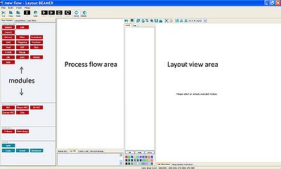
To use the modules, they are dragged to the process flow area.
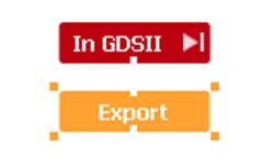
The inputs and outputs of each module are illustrated by white tags. Two modules are coupled to each other by positioning the input of e.g. the Export module on top of the output of the Import module. The input/output tags turns black when they are connected.
By clicking on active modules, the layout of the file becomes visible in the layout view area.
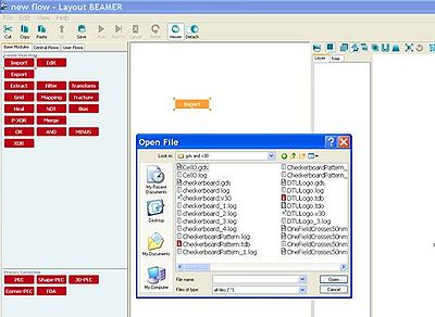
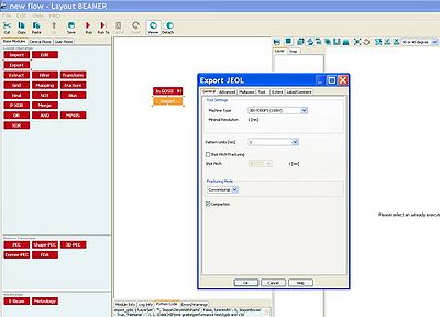
Simple conversion from GDSII to v30
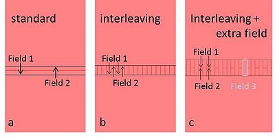
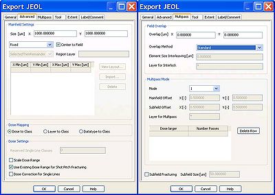
If your pattern is larger than one field size, it will be stitched by several fields. In the tab 'Multipass', you can choose to smooth the stitching errors by overlapping the fields to be stitched or by multipass method.
There are 3 types of overlap methods; for all 3 methods you define an overlap width:
standard: the overlap will be exposed with half dose both of field 1 and field2; interleaving: the overlap will be finger-jointed by field 1 and field 2; interleaving with extra field: the overlap will be finger-jointed by field 1, field 2 and an extra field 3, as illustrated below in figure c.
The multipass method smooths the pattern writing over many fields, each field writing the pattern with e.g. half the dose in different areas of the main deflector; this is however not recommended for field sizes larger than 500 mm x 500 mm, as the distorion of the main deflector using larger field sizes may be larger than the stitching errors of two fields.
Dose variations
Dose variation defined by datatype or layertype
When designing your pattern, you can define a dose variation either by defining different areas in different GDS datatype or in different layertype.
In both cases you import the GDS-file as usual into BEAMER, importing all layers. The layers should be visible when you view the GDSfile:
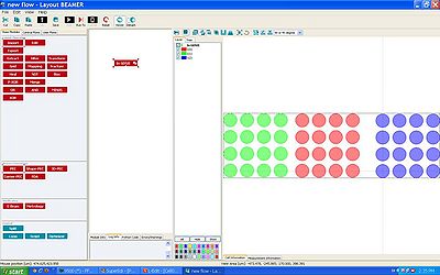
If you defined different doses by different GDS layers, you should tick 'Datatype to Class' under 'Advanced' when you convert to v30.
If you defined different doses by different layer type, you should tick 'Layer to Class' under 'Advanced' when you convert to v30.
View the v30-file and make sure all variations have been converted correctly.
In the jdf-file, manually create a shot modulation (similar to the jdi-file created by PEC) that fits to the number of layers in your v30-file. This shot modulation should be defined in the end of the jdf-file (see the sdf- and jdf-file manual). In the example below, the six layers are defined to have shot modulation from -20 % to 80 % of the base-dose:
JOB/W  'TEST',4         ; 4 inch wafer
PATH DTU5M
  ARRAY    (0,1,0)/(10000,3,10000)
    ASSIGN  P(1)-> ((*,*),SHOT1)
  AEND
PEND


LAYER    1
P(1)  'fredrikpnov1507prox.v30'
SPPRM 4.0,,,,1.0,1
STDCUR 0.22   ;nA

SHOT1:  MODULAT   (( 0, -20) , ( 1, 0) , ( 2, 20)
-     , ( 3, 40 ) , ( 4, 60 ) , ( 5, 80))

END
Dose variation defined by an array in jdf file
It is easy to repeat the pattern (v30-file) in an array with different doses in the jdf file, just type the dose modulation you wish to apply to every chip in the array:
JOB/W  'TEST',4         ; 4 inch wafer
PATH DTU5M
  ARRAY    (-10000,2,10000)/(10000,1,10000)
    ASSIGN  P(1)-> ((1,1),SHOT1)
    ASSIGN  P(1)-> ((1,2),SHOT1)
    ASSIGN  P(1)-> ((2,1),SHOT1)
    ASSIGN  P(1)-> ((2,2),SHOT1)
  AEND
PEND


LAYER    1
P(1)  'tjulahej.v30'
SPPRM 4.0,,,,1.0,1
STDCUR 0.22   ;nA

SHOT1:  MODULAT   (( 0, -20))
SHOT2:  MODULAT   (( 0, -10))
SHOT3:  MODULAT   (( 0, 0))
SHOT4:  MODULAT   (( 0, 10))

END
Proximity Error Correction (PEC)
BEAMER has a built-in proximity error correction simulation program; import the GDS-file as usual and connect the 'PEC' module to its output. In the 'Proximity Error Correction' window you can either type Beta and Eta manually or import a point spread function (PSF).
After converting to v30-format, the dose variation is illustrated in your pattern:
BEAMER has at this point created a jdi-file in the same folder as the v30-file. This jdi-file is the shot modulation that should be inserted in the jdf-file (see section 4 in the sdf- and jdf-file preparation manual). The jdi-file opens with SuperEdi.
Bulk and sleeve
If you have structures with both bulky and fine parts that you wish to pattern either with different doses or different currents, you can use BEAMER to divide the structures in different layers or different v30-files.
Below, an illustration of how this is done by using the Bias and Minus modules; the Bias function subtracts in this case 1 micron from the pattern, defining layer 0 (red layer). Layer 1 (green) is the original pattern minus layer 0.
In the flow to the left, the two layers are exported separately in two different v30-files. In the flow to the right, the two layers are combined in one single v30-file:

