Specific Process Knowledge/Etch/DRIE-Pegasus/System-description: Difference between revisions
| Line 78: | Line 78: | ||
[[File:RF matching 2.jpg|600px|thumb]] | [[File:RF matching 2.jpg|600px|thumb]] | ||
One can see that | One can see that when the pressure changes, the matching network responds and settles in new positions. | ||
Revision as of 14:42, 15 May 2018
Feedback to this page: click here
Description of the Bosch process at the DRIE-Pegasus
--jmli (talk) 26 November 2012
The DRIE-Pegasus takes the well established Bosch process known from the ASE a significant step further. In the ASE the Bosch process has two cycles, etch and passivation. During each cycle the process parameters are kept constant:
- In the passivation cycle, a C4F8 plasma is formed using the RF coil power only and a teflon-like coating is created on all surfaces thus protecting the sidewalls in the subsequent etch cycle.
- In the etch cycle
- the ion bombardment driven by the platen power first removes the passivation layer on the surfaces directly exposed to the ions (i.e. horizontal surfaces)
- then as the bottom of the structures are opened the etch of silicon itself starts.

Here, it is clear that one can distinguish two phases of the etch cycle; one where the ion bombardment removes the polymer and one where the actual etching of silicon takes place. Considering what process conditions are favorable we realize that
- the ion bombardment requires a low pressure in order for the ions to have a long mean free path and hence good directionality. Also, a high platen power is required to drive the ion bombardment.
- a higher pressure during the etch increases the density of reactive species and hence the etch rate. Since a high platen power is no longer necessary to drive the ion bombardement, lowering it will reduce the impact on the masking material thus improving the selectivity.
These conflicting demands are the same on the ASE. However, with hardware improvements on the DRIE-Pegasus such as
- fast response digtal MFC's mounted on top of the process chamber itself to shorten the gas line
- fast APC valve
- fast RF power supplies
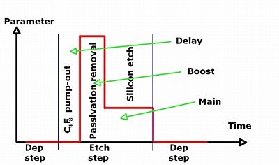
the etch and deposition cycles may be split into three separate phases, called Delay, Boost and Main. Following the arguments from above, the third phase (Delay) may be thought of as a short delay that ensures a very low pressure (and thus extremely good ion directionality) before the ion bombardment. The standard etches on the Pegasus only make use of up to two phases.
Processing options on the Pegasus
--jmli (talk) 26 November 2012
The Pegasus has a lot of advanced processing options.
- Multiplexing: As described above, the multiplexed Bosch process may have the etch or passivation cycle each split into three separate phases: Delay, Boost and Main.
- Ramping:Using the ramp option one can change process parameters linearly over the course of each processing step.
- Process steps: Stich any number of processing steps with different parameters to make one continuous process.
- Hardware: The Pegasus has several hardware settings:
- Spacers : The distance to the plasma source may be changed by using different spacers.
- Baffle and funnel: The funnel inside the chamber helps to focus the plasma/ions towards the electrode. They may be taken out but don't expect this option to be part of the parameters that you can change in your experiments.
This gives an infinite process parameter space....
Improving the Bosch process by modifying the showerhead
--jmli (talk) 20 November 2015
It is clear that optimizing the Bosch processes on the Pegasus can be done in countless ways. Reducing the cycle time is a very convenient way of getting rid of, or at least reducing, scallops. The faster the process switches the smaller the scallops will be. However, at some point the hardware (MFS's, RF generators, APC valve) cannot keep up with the demand and the process will essentially be continuous causing the Bosch process to break down. In its original setup, the Pegasus had standard processes with cycle durations down to 2 seconds. The hardware on the Pegasus is indeed very fast and allows faster switching. The limiting factor in the Bosch process was identified by Henri Jansen - and we have taken steps to improve this as described below.
In the top of the plasma source sits a showerhead that is intended to distribute the process gasses uniformly so that a uniform etch process is achieved. However, calculations showed that the resistance imposed on the gasses flowing through small holes caused by small holes in the showerhead. The showerhead that distributes the process gasses inside the plasma source has been changed. With the new design the gas flow resistance in the gas line from MFC to plasma has been reduced. This has very little or no impact on processes that have a continuous gas flow - i.e. processes that are not switched. However, for processes with several gas flows that switch on and off, the switching from one gas flow to another will be much more well defined. This enables us to run Bosch processes with shorter cycles times. Shorter cycles times means smaller scallops and hence lower roughness and better control.
As stated, we believe that only switched processes will be affected by this change. Continuous processes such as Process C, Nano1.42, isotropic etches, barc etches or the black silicon recipes are not believed to be noticeably affected.
Click HERE to see a comparison of some the etches before and after the change of the showerhead.
A closer look at the Bosch Process
A few words about RF matching in general
(This section contains material from the Dry Etch TPT lecture)
Connecting a RF generator to an AC circuit in order to drive a plasma in a dry etch tool is not as trivial as one might expect. One cannot just connect an RF generator to a coil, put a certain power through and expect a plasma generated absorb all energy. It is not possible: At RF frequencies even cables become inductors so circuits must be carefully constructed.
Most power RF generators are designed to transfer power into a 50 ohm load. This means that the circuit, in addition to the coil that has a certain inductance and resistance will also require additional electrical components if the total 50 ohm impedance criteria is to be met (unless the inductance and resistance of the coil are carefully chosen and constant). If the impedance is off, part of the power will be dissipated as Reflected Power for instance localized heating of RF cables due to standing waves. One must therefore have a way of controlling the circuit impedance.
The matching unit consists of two tunable capacitors and an impedance matching network. The network measures the impedance of the circuit and automatically changes the capacitances of the capacitors (called Load and Tune) in order to match the 50 ohm impedance. The changing of the active area inside the capacitor is done by rotating the shaft as illustrated above. It is unrealistic to achieved perfect matching (zero reflected power) so some minimum value (always less than 10 % of the input power) is found.
This is, however, by no means a simple matter and the setpoints of Load and Tune (always measured as percentages of full capacitance) must be chosen wisely or the RF matching will fail. Therefore, if the setpoints for Load and Tune in a recipe are wrong - the process will fail and most likely abort.
Once a plasma has been ignited in the process chamber by the coil, an electron current will be induced in the conductive part of the plasma so as to oppose the RF magnetic field. As a result of the coupling between the coil and the plasma, the inductance of the coil changes. This, in turn, changes the impedance of the generator circuit and the matching network ensures that the impedance matching is still preserved.
Why RF matching is extremely important in the Bosch process
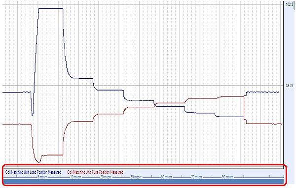
In the continuous processes (that means fixed parameters that do not change during the process) that are used in most dry etch tools the action of the impedance matching network is mostly seen in the beginning of the process when the plasma stabilizes. Once stabilized and a minimum reflected power has been established, the capacitors usually needs only minor adjustments. Below is a datalog of an oxygen cleaning process running with:
- 100 sccm O2
- 1200 W coil power
- 20 W platen power
- Automatic matching
showing the values of the Load (blue) and Tune (red) positions. The only process parameter that changes is the pressure - along the X axis one can see the different pressure settings.

One can see that when the pressure changes, the matching network responds and settles in new positions.

