Specific Process Knowledge/Thermal Process/Oxidation/Wet oxidation C1 furnace: Difference between revisions
| Line 23: | Line 23: | ||
''' | ''' | ||
====Experimental setup (1)==== | ====Experimental setup (1) Effect screening==== | ||
''' | ''' | ||
The boat was fully filled with dummy wafers, and there are three tested wafers per run. The three tested wafers were placed at slot number 6, 15 and 24. The average silicon dioxide thickness and the percent of film non-uniformity over the boat were calculated form those three test wafers. The average silicon dioxide thickness and the percent of film non-uniformity over the wafer was calculated from the wafer slot no.15, which was placed in the middle of the boat. | The boat was fully filled with dummy wafers, and there are three tested wafers per run. The three tested wafers were placed at slot number 6, 15 and 24. The average silicon dioxide thickness and the percent of film non-uniformity over the boat were calculated form those three test wafers. The average silicon dioxide thickness and the percent of film non-uniformity over the wafer was calculated from the wafer slot no.15, which was placed in the middle of the boat. | ||
Revision as of 13:14, 30 September 2014
THIS PAGE IS UNDER CONSTRUCTION
Feedback to this page: click here
The wet oxidation by Anneal Oxide Furnace(C1) can be used for growing silicon dioxide by using steamer (RASIRC Steam Generator ), which gives a very good film uniformity.
Calculation for wet oxidation
The following links give an approximate oxide time/thickness based on prediction equations from the following experiments:
Test of the wet oxidation by steamer
Purpose
To study the effect of the process temperature, growth time and steamer flow on the silicon dioxide thinkness and the percent of film non-uniformity.
Experimental setup (1) Effect screening
The boat was fully filled with dummy wafers, and there are three tested wafers per run. The three tested wafers were placed at slot number 6, 15 and 24. The average silicon dioxide thickness and the percent of film non-uniformity over the boat were calculated form those three test wafers. The average silicon dioxide thickness and the percent of film non-uniformity over the wafer was calculated from the wafer slot no.15, which was placed in the middle of the boat.
Pressure: Atmosphere
Temperature: 1000, 1050, 1100 C
Time: 15, 180, 360, 720 minutes
Steamer Flow Rate: 10, 17.5, 25 L/min
Anneal: Same as process temperature for 20 minutes with N2: 6 SLM
Test Wafers: N-Type <100> No RCA Clean
Results (1)
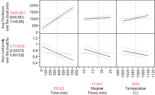
The figure 1 shown that the silicon dioxide thickness over the boat is affected the most by process time, temperature and steamer flow rate respectively. When the process time, temperature and steamer flow rate increase, the silicon dioxide thickness also increases. Since the steamer flow has the least an effect to the silicon dioxide thickness, so the flow rate has been fixed at 10 liter per minutes in the furnace recipe.
Figure 1. The average silicon dioxide thickness and the percent of film non-uniformity over the boat variation with process time, steamer flow rate and temperature.
The percent of film non-uniformity over the boat most likely depends on the silicon dioxide thickness. The thicker silicon dioxide gives better film uniformity. The figure 1 shown that the percent of film non-uniformity over the boat decreases, when the process time, steamer flow rate and the temperature increase.
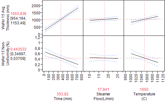
Figure 2. The average silicon dioxide thickness and the percent of film non-uniformity over the wafer variation with process time, steamer flow rate and temperature.
The effect of the steamer flow rate, process time and temperature to the silicon dioxide thickness and to the percent of film non-uniformity over the wafer is quite similar with over the boat. But the percent of film non-uniformity over the boat is lower than over the boat, and the steamer flow has almost no an effect on the film uniformity.
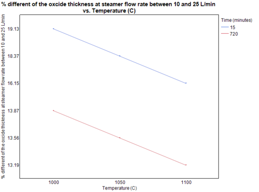
Figure 3. The percent different of the silicon dioxide thickness at the steamer flow rate at 10 and 25 l/min variation with temperature.
The figure 3 shown that the percent different of silicon dioxide thickness deceases when the process temperature and time increase, which means that the steamer flow rate has less effect on the thicker silicon dioxide film.
Experimental setup (2)
The boat was fully filled with dummy wafers, and there are three tested wafers per run. The three tested wafers were placed at slot number 6, 15 and 24. The average silicon dioxide thickness and the percent of film non-uniformity over the boat were calculated form those three test wafers. The average silicon dioxide thickness and the percent of film non-uniformity over the wafer was calculated from the wafer slot no.15, which was placed in the middle of the boat.
Pressure: Atmosphere
Temperature: 1000, 1050, 1100 C
Time: 0, 5, 15, 100, 180,250, 360, 720 minutes
Steamer Flow Rate: 10 L/min
Anneal: Same as process temperature for 20 minutes with N2: 6 SLM
Test Wafers: N-Type <100> No RCA Clean
Results (2)
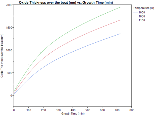
Figure 4. Silicon dioxide thickness variation with growth time (from 0 to 720 minutes) in different temperature.
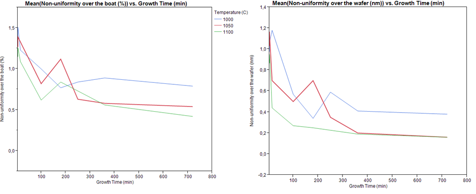
Figure 5. The percent of film non-uniformity variation with growth time in different temperature. (left) Over the boat and (right) over the wafer
From figure 5 shown that the percent of film non-uniformity deceases when the process time and process temperature increase. From this experiment, show that the silicon dioxide has a very good uniformity. The percent of film non-uniformity is lower than 1.5 over the boat, and lower than 1.2 over the wafer.

