LabAdviser/314/Microscopy 314-307/Technique/Holo/Off-axis ETEM: Difference between revisions
| (3 intermediate revisions by the same user not shown) | |||
| Line 14: | Line 14: | ||
In order to remove effects from the TEM or other instabilities, reference holograms are usually acquired right after the object holograms. They are later used for reconstruction. | In order to remove effects from the TEM or other instabilities, reference holograms are usually acquired right after the object holograms. They are later used for reconstruction. | ||
[[file:Schematic_holo.jpg|thumb|left|200px|Figure 1: Schematic of the set-up for off-axis electron holography. U0 is the biprism voltage, s is the fringe spacing, β is the angle that the object and reference wave is superimposed onto one another, and w is the width of the interference pattern.]] <br clear=all | :[[file:Schematic_holo.jpg|thumb|left|200px|Figure 1: Schematic of the set-up for off-axis electron holography. U0 is the biprism voltage, s is the fringe spacing, β is the angle that the object and reference wave is superimposed onto one another, and w is the width of the interference pattern.]] <br clear=all> | ||
The detailed procedure for obtaining electron holograms is described below. The procedure has been used for obtaining holograms of in liquid phase transmission electron microscopy or of single features on a C-grid. Some tips are also shown at the end of the document. | The detailed procedure for obtaining electron holograms is described below. The procedure has been used for obtaining holograms of in liquid phase transmission electron microscopy or of single features on a C-grid. Some tips are also shown at the end of the document. | ||
| Line 24: | Line 24: | ||
# Fill Liquid nitrogen in the dewar twice or thrice -once at the beginning of the session prior to inserting the TEM holder, once after 30 minutes into the session, and the once around half time of the full-day session. | # Fill Liquid nitrogen in the dewar twice or thrice -once at the beginning of the session prior to inserting the TEM holder, once after 30 minutes into the session, and the once around half time of the full-day session. | ||
# Switch on the power supply at the backside of the room (the display will show 0V and 0A when turned on) | # Switch on the power supply at the backside of the room (the display will show 0V and 0A when turned on) | ||
#:[[file:Holo-power-supply_ETEM.jpg|thumb|left|200px|Figure 2: Power supply]] <br clear=all | #:[[file:Holo-power-supply_ETEM.jpg|thumb|left|200px|Figure 2: Power supply]] <br clear=all> | ||
# Switch on the control box (under the microscope PC) (ensure the polarity is at +V, -V would diverge the reference and object wave) | # Switch on the control box (under the microscope PC) (ensure the polarity is at +V, -V would diverge the reference and object wave) | ||
#:[[file:Holo-control-box_ETEM.jpg|thumb|left|200px|Figure 3: Control box]] <br clear=all | #:[[file:Holo-control-box_ETEM.jpg|thumb|left|200px|Figure 3: Control box]] <br clear=all> | ||
# Switch cables on SAD from the wire saying “Ground” to the wire saying “Power” | # Switch cables on SAD from the wire saying “Ground” to the wire saying “Power” | ||
#:[[file:Holo-cable_ETEM.jpg|thumb|left|200px|Figure 4: Cable for biprism]] <br clear=all | #:[[file:Holo-cable_ETEM.jpg|thumb|left|200px|Figure 4: Cable for biprism]] <br clear=all> | ||
# Insert your holder. First reset the holder such that the compustage is at x,y,z = 0,0,0, and both α and β tilt is at zero degrees. The insertion of the holder is similar to normal, by first parking the holder in the air-lock vent cycle (10min). Afterwards, rotate the holder to 12 o’clock and insert the holder slowly (the vacuum from the column will slowly pull it in) | # Insert your holder. First reset the holder such that the compustage is at x,y,z = 0,0,0, and both α and β tilt is at zero degrees. The insertion of the holder is similar to normal, by first parking the holder in the air-lock vent cycle (10min). Afterwards, rotate the holder to 12 o’clock and insert the holder slowly (the vacuum from the column will slowly pull it in) | ||
# Find the specimen and ensure the beam is centered (Beam Alignment) | # Find the specimen and ensure the beam is centered (Beam Alignment) | ||
| Line 63: | Line 63: | ||
# Insert the biprism. Insert the SAD aperture (lever from left to right – remember to hold a finger so the spring doesn’t “jump”, which may break the biprism!). Position of the biprism is SAD aperture #1. Find the biprism and center it. If you can’t see it, excite the biprism to ~100 V with the volume knob on the controls for the biprism. | # Insert the biprism. Insert the SAD aperture (lever from left to right – remember to hold a finger so the spring doesn’t “jump”, which may break the biprism!). Position of the biprism is SAD aperture #1. Find the biprism and center it. If you can’t see it, excite the biprism to ~100 V with the volume knob on the controls for the biprism. | ||
#* If it is still not visible, move the aperture till you can see the edge of the aperture. Move One of the knobs (slowly) till you see a white line (at low mag)/interference pattern → This is the interference pattern | #* If it is still not visible, move the aperture till you can see the edge of the aperture. Move One of the knobs (slowly) till you see a white line (at low mag)/interference pattern → This is the interference pattern | ||
#:[[file:Holo-control-box-setting_ETEM.png|thumb|left|200px|Figure 5: Exciting the biprism through control box]] <br clear=all | #:[[file:Holo-control-box-setting_ETEM.png|thumb|left|200px|Figure 5: Exciting the biprism through control box]] <br clear=all> | ||
# Align the biprism to the feature of interest. Usually the biprism should be at an angle to the feature, e.g. a straight line. When aligning the biprism, one has to consider where the object and reference wave are passed through. If the biprism is perpendicular to the feature, the reference and object wave both passes through that feature and would terminate each other. Therefore, the reference wave is usually passed through vacuum/substrate and the object wave over that feature. Rotate the biprism with the black knob on the SAD aperture (outermost knob). You may want to zoom out to not lose the biprism from the FOV | # Align the biprism to the feature of interest. Usually the biprism should be at an angle to the feature, e.g. a straight line. When aligning the biprism, one has to consider where the object and reference wave are passed through. If the biprism is perpendicular to the feature, the reference and object wave both passes through that feature and would terminate each other. Therefore, the reference wave is usually passed through vacuum/substrate and the object wave over that feature. Rotate the biprism with the black knob on the SAD aperture (outermost knob). You may want to zoom out to not lose the biprism from the FOV | ||
# Align the beam to the biprism. The beam should be elliptical and perpendicular to the biprism to achieve high spatial coherence. Aligning the beam is done by stigmating the beam through the condenser lens. For this: Press stigmator → Condenser Stigmation → Rotate MFx or MFy. Note, either MFx or MFy has to be at their maximum, e.g. MFx = +1 or -1. When that is fixed, rotate the other multifunction knob until the beam is perpendicular to the biprism. In order to see if the beam is aligned to the biprism, check for the “step” that is produced when condensing the beam (Intensity knob). The idea is illustrated in the figure below. | # Align the beam to the biprism. The beam should be elliptical and perpendicular to the biprism to achieve high spatial coherence. Aligning the beam is done by stigmating the beam through the condenser lens. For this: Press stigmator → Condenser Stigmation → Rotate MFx or MFy. Note, either MFx or MFy has to be at their maximum, e.g. MFx = +1 or -1. When that is fixed, rotate the other multifunction knob until the beam is perpendicular to the biprism. In order to see if the beam is aligned to the biprism, check for the “step” that is produced when condensing the beam (Intensity knob). The idea is illustrated in the figure below. | ||
#:[[file:Holo-beam-alignment.png|thumb|left|200px|Figure 6: Aligning the beam (schematic)]] <br clear=all | #:[[file:Holo-beam-alignment.png|thumb|left|200px|Figure 6: Aligning the beam (schematic)]] <br clear=all> | ||
# Recheck the alignments: Rotation Center, PPx/PPy, Beam shift and object astigmatism. Most crucial is rotation center and object astigmatism! | # Recheck the alignments: Rotation Center, PPx/PPy, Beam shift and object astigmatism. Most crucial is rotation center and object astigmatism! | ||
# Tune the biprism voltage: Usually around 150-180V is useful, but higher voltages can be used for better resolution. Note that the fringes should be separated enough to see the individual fringes + it is recommended that 4 pixels per fringe is the minimum of fringe width. | # Tune the biprism voltage: Usually around 150-180V is useful, but higher voltages can be used for better resolution. Note that the fringes should be separated enough to see the individual fringes + it is recommended that 4 pixels per fringe is the minimum of fringe width. | ||
| Line 116: | Line 116: | ||
== Notes/Tips == | == Notes/Tips == | ||
# Black lines appear in the image | # Black lines appear in the image: | ||
# | #: [[file:Holo-artefact-frindges.jpg|thumb|left|200px|Figure 7: black line artefact in frindge image]] <br clear=all> | ||
#: This occurs due to the dark/Gain reference image is not correct. In order to fix this, remove the biprism/SAD (lever from left to right). Reset the FEG (Gun tab → FEG Register → Choose the correct register → Click on Set) and set it to TEM mode (Gun → BeamSettings → Click on TEM button) | #: This occurs due to the dark/Gain reference image is not correct. In order to fix this, remove the biprism/SAD (lever from left to right). Reset the FEG (Gun tab → FEG Register → Choose the correct register → Click on Set) and set it to TEM mode (Gun → BeamSettings → Click on TEM button) | ||
#: First, prepare the gain reference: One the OneView Computer (GMS3), go to Help → User → Power User. Lift the screen (R1) | #: First, prepare the gain reference: One the OneView Computer (GMS3), go to Help → User → Power User. Lift the screen (R1) | ||
| Line 131: | Line 131: | ||
# If you see a blister on the biprism, it means the biprism is contaminated at this region. Move the biprism by adjusting the knobs on the SAD aperture until the blister is not there | # If you see a blister on the biprism, it means the biprism is contaminated at this region. Move the biprism by adjusting the knobs on the SAD aperture until the blister is not there | ||
#* You don’t want a curved interference pattern, the lines should be straight | #* You don’t want a curved interference pattern, the lines should be straight | ||
# Do not jump around or cause vibrations | # Do not jump around or cause vibrations → Move the chair and yourself away from the desk if necessary | ||
# If the biprism is not stable, even after waiting, tab either of the knobs of the SAD ever so slightly. It is possible the SAD aperture is moving, tabbing will help it fall into a stable position. | # If the biprism is not stable, even after waiting, tab either of the knobs of the SAD ever so slightly. It is possible the SAD aperture is moving, tabbing will help it fall into a stable position. | ||
# Name the reference and object holograms appropriately. I usually have a string for the file along the lines: Sample_Magnification_BiprismVoltage_ExposureTime_Obj_Number for object holograms, and “Obj” is “Ref” for reference holograms. | # Name the reference and object holograms appropriately. I usually have a string for the file along the lines: Sample_Magnification_BiprismVoltage_ExposureTime_Obj_Number for object holograms, and “Obj” is “Ref” for reference holograms. | ||
#* You need to know the biprism voltage and exposure time for later documentation, since these values determine the width and carrier frequency and are always reported in literature. | #* You need to know the biprism voltage and exposure time for later documentation, since these values determine the width and carrier frequency and are always reported in literature. | ||
Latest revision as of 10:22, 7 May 2024
Feedback to this page: click here
THIS PAGE IS UNDER CONSTRUCTION
(content by Mads Søndergaard Larsen @DTU Nanolab, May 2024)
Electron Holography on the ETEM
Off-axis electron holography is a transmission electron microscopy technique that is sensitive to the phase of the electrons passing through the specimen. The measurement of phase changes of electrons is very important for measuring material properties like mean inner potential and built-in potential. It is also very important in measuring charge distribution across specimens at a high spatial resolution. In this technique a part of the electron beam passes through the specimen and the other part passes through vacuum. A biprism wire (see the below figure) in the plane of the SAD apertures is held at a fixed potential and this creates an interference pattern between the electrons passing through the specimen (object wave) and vacuum/support (reference wave). The biprism can be put anywhere in the imaging system, however it is easiest to have it in the SAD plane due to the apertures being retractable and modified. The most important thing for holography is where the first intermediate image is formed, which needs to be out of plane from the biprism in order for the waves to produce the interference pattern (see https://doi.org/10.1016/0304-3991(96)00017-4). In order to remove effects from the TEM or other instabilities, reference holograms are usually acquired right after the object holograms. They are later used for reconstruction.
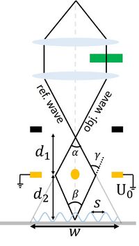
Figure 1: Schematic of the set-up for off-axis electron holography. U0 is the biprism voltage, s is the fringe spacing, β is the angle that the object and reference wave is superimposed onto one another, and w is the width of the interference pattern.

The detailed procedure for obtaining electron holograms is described below. The procedure has been used for obtaining holograms of in liquid phase transmission electron microscopy or of single features on a C-grid. Some tips are also shown at the end of the document.
Procedure for Performing Electron Holography in ETEM
Setting up the ETEM for Holography
- Fill Liquid nitrogen in the dewar twice or thrice -once at the beginning of the session prior to inserting the TEM holder, once after 30 minutes into the session, and the once around half time of the full-day session.
- Switch on the power supply at the backside of the room (the display will show 0V and 0A when turned on)
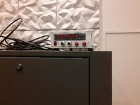
Figure 2: Power supply
- Switch on the control box (under the microscope PC) (ensure the polarity is at +V, -V would diverge the reference and object wave)
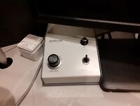
Figure 3: Control box
- Switch cables on SAD from the wire saying “Ground” to the wire saying “Power”
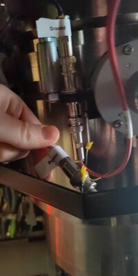
Figure 4: Cable for biprism
- Insert your holder. First reset the holder such that the compustage is at x,y,z = 0,0,0, and both α and β tilt is at zero degrees. The insertion of the holder is similar to normal, by first parking the holder in the air-lock vent cycle (10min). Afterwards, rotate the holder to 12 o’clock and insert the holder slowly (the vacuum from the column will slowly pull it in)
- Find the specimen and ensure the beam is centered (Beam Alignment)
- If needed (alignment is way off): Load the appropriate TEM alignment, e.g. 300 kV TEM. This is done by going to Alignment tab → Alignment → Flapout → load the alignment file for the correct keV, e.g. Main_300kV. Select one particular alignment and the press Ctrl+A for selecting all and then move them from “Available” to “Selected” by clicking on the Apply button.
- If needed: Load the FEG register for TEM for the electron energy chosen in step 5 above. This is done by going to Gun tab → FEG Register → Choose the correct register → Click on Set
- Make sure that the size of C2 aperture is set to 150 µm. Go to Mono tab → Aperture → C2 → adjust and play with multifunctional knobs MFx and MFy on the left and right control panels for centering the chosen C2 aperture.
- lower C2 aperture can be used, however some of the beam is not passed through and can have an impact on the holograms.
- Adjust the monochromator so that is does not interfere with the image
- Translational alignment of the monochromator: Go to the Monochromator panel → click on shift and play with MFx and MFy to center the monochromator around the beam
- Strength of the monochromator: While in the monochromator panel, unclick the shift (yellow to grey) and click the focus button. Adjust the strength of the monochromator with the intensity (Mono = -30 → -40 is usually the range).
- The dose can further be reduced at lower Mono values, e.g. -100 or lower (adjust for different samples, however you need enough electrons to obtain good holograms. Test this when reconstructing if needed)
- Insert the OneView (CMOS) camera. Make sure the BM-Ultrascan is retracted. Go to the Oneview PC → Microscope Display → Click the Camera Icon → “Insert”.
- Open the display of the camera: Click TEM Imaging/Holography → “View”
- Depending on the resolution, two different routes are needed. For medium resolution, I advice using Lorentz mode, which uses a weaker Lorentz lens and switches off the twin-pole object lens. For high-resolution, use the conventional HR-TEM mode.


Medium Resolution Holography:
Unfortunately, the image corrector has not been aligned to Lorentz mode, so any object astigmatism needs to be corrected manually. However, this is not an issue, since the medium resolution usually does not require the aid of the image corrector (you see features > 10nm).
- Go to the last tab (Lorentz) and switch on Lorentz mode (click the Lorentz Mode button) → It will turn yellow when enabled
- The screen will now read: Ltz Probe
- Turn the magnification to Mh mode by rotating the magnification know clockwise. The first intermediate image in the SA mode occurs directly in the SAD plane (where the biprism sits), Mh mode is forming the image below this plane, which is necessary for holography as detailed earlier.
- Rotate the magnification knob (clockwise) to the lowest Mh mode (135X) such that you can see the beam. Center the beam by Beam Shift and increase the magnification and ensure the beam is centered (counter clockwise rotation of the magnification knob)
- Find a suitable feature to align to, e.g. a NP or the edge of a C-grid
- Adjust the eucentric height by Z-adjustment. The Lorentz lens has a different focal length than the object lens, so the eucentric height has changed (up to -100µm)
- Adjust the pivot points: Go to Aligment Tab → PPx/PPy. Adjust the MFx and MFy to ensure the beam does not jump around on the phosphorous screen
- The camera can be helpful for fine tuning: Remove the phosphorous screen (R1 on the right panel) and view the image on the Oneview computer
- Adjust the rotation center: Go to the Alignment tab Rotation center. The image will wobble, you want to ensure that the feature only wobbles in and out of focus.
- Move the sample to an area with an amorphous film to align the object astigmatism
- Lift the screen: R1 on the right panel
- In the GMS 3 on the Oneview computer, press crtl + shift + F to open a live FFT
- Defocus the object lens a bit: Focus → Rotate counter clock wise
- Press the stigmator button → Object stigmation → Rotate MFx and MFy
- Align the Thon Rings, such that they are circular in the FFT
- Insert the biprism. Insert the SAD aperture (lever from left to right – remember to hold a finger so the spring doesn’t “jump”, which may break the biprism!). Position of the biprism is SAD aperture #1. Find the biprism and center it. If you can’t see it, excite the biprism to ~100 V with the volume knob on the controls for the biprism.
- If it is still not visible, move the aperture till you can see the edge of the aperture. Move One of the knobs (slowly) till you see a white line (at low mag)/interference pattern → This is the interference pattern

Figure 5: Exciting the biprism through control box
- Align the biprism to the feature of interest. Usually the biprism should be at an angle to the feature, e.g. a straight line. When aligning the biprism, one has to consider where the object and reference wave are passed through. If the biprism is perpendicular to the feature, the reference and object wave both passes through that feature and would terminate each other. Therefore, the reference wave is usually passed through vacuum/substrate and the object wave over that feature. Rotate the biprism with the black knob on the SAD aperture (outermost knob). You may want to zoom out to not lose the biprism from the FOV
- Align the beam to the biprism. The beam should be elliptical and perpendicular to the biprism to achieve high spatial coherence. Aligning the beam is done by stigmating the beam through the condenser lens. For this: Press stigmator → Condenser Stigmation → Rotate MFx or MFy. Note, either MFx or MFy has to be at their maximum, e.g. MFx = +1 or -1. When that is fixed, rotate the other multifunction knob until the beam is perpendicular to the biprism. In order to see if the beam is aligned to the biprism, check for the “step” that is produced when condensing the beam (Intensity knob). The idea is illustrated in the figure below.

Figure 6: Aligning the beam (schematic)
- Recheck the alignments: Rotation Center, PPx/PPy, Beam shift and object astigmatism. Most crucial is rotation center and object astigmatism!
- Tune the biprism voltage: Usually around 150-180V is useful, but higher voltages can be used for better resolution. Note that the fringes should be separated enough to see the individual fringes + it is recommended that 4 pixels per fringe is the minimum of fringe width.
- Acquire a reference hologram and ensure the biprism does not drift: Oneview PC → Exposure time (4s/8s or higher) and check that it does not drift when acquiring
- If it drifts, either move away from the desk (you may cause vibrations yourself) or wait a few minutes for the biprism to stabilize at the voltage used.
- Acquire object and reference holograms at the desired exposure time → “Acquire”


HR-Electron Holography
The steps for alignment of the biprism is similar to the Medium Resolution case.
- Make sure that you are working with the C3 off: Gun tab → Free Ctrl → C3 off
- Go to Mh mode by turning the magnification knob counter clockwise
- Fix rotation center and PPx/PPy (Alignments)
- For object astigmatism, instead of doing it manually, we will instead use the image corrector for alignment. Follow the manual from J. Kling (LabManager → Info → Titan E-Cell 80-300ST → Documents → “Titan_ImageCorrector_ETEM_20190118” (or something similar)
- Follow steps 8-11 and 13-14 from Medium Resolution Holography
- Don’t change image corrector settings → It will not work when the interference pattern is there!
Finishing-up the Holography Part of the Measurements
- Stop the camera acquisition
- Put the viewing screen down (with R1 button)
- Reset the TEM to its initial conditions:
- Switch to TEM mode (Gun → BeamSettings → Click on TEM button).Turn down the volume knob of the biprism. Then turn off this box.
- Reset the FEG: Gun tab → FEG Register → Choose the correct register → Click on Set
- This will reset the monochromator to its initial state aswell
- Turn off the power supply box in the back of the room.
- Swap the cables at the SAD apertures (from “Power” to “Ground”)
- Remove the biprism/SAD aperture (lever from left to right)
Image Analysis in GMS3
Instead of relying solely on post-mortem image analysis, GMS3 on the ETEM has the necessary image analysis for holograms. To do in-situ image analysis, the Holography mode in GMS3 can be used.
- Click the Holo3 tab: Reconstruct
- If you have a reference hologram acquired, specify this in the pop-up window.
- Check off the “Choose sideband manually” (it is unchecked per default)
- In the pop-up FFT, click either of the sidebands by left-click
- Press enter
- Set the radius of the applied mask → The default of 1/3 the distance to the center band is usually sufficient
- Afterwards, 3 windows will open: The amplitude image (“A”) and the phase image (“P”) and the contrast (“C”)
- If you want to unwrap the phase:
- Click the phase image (“P”)
- Right click the image and select ROI
- Draw the ROI over the interference pattern (you don’t need to unwrap parts outside the interference pattern)
- In the holography section, click “Unwrap Phase”
- Draw line profiles in the unwrapped phase and measure the potential (e.g. the MIP)
- You can increase the ROI by pressing crtl+
- window will also pop up, the width is set by the pixel size of the ROI
Notes/Tips
- Black lines appear in the image:
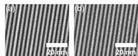
Figure 7: black line artefact in frindge image - This occurs due to the dark/Gain reference image is not correct. In order to fix this, remove the biprism/SAD (lever from left to right). Reset the FEG (Gun tab → FEG Register → Choose the correct register → Click on Set) and set it to TEM mode (Gun → BeamSettings → Click on TEM button)
- First, prepare the gain reference: One the OneView Computer (GMS3), go to Help → User → Power User. Lift the screen (R1)
- In GMS3 click camera → Prepare Gain reference → Follow the directions in GMS3 by tuning the condenser lens strength (Intensity) to a signal of 1000e- and later 4000e- (tune the monochromator if necessary)
- After Gain reference, prepare dark reference by first lowering the screen and turning off the beam (Column valves): In GMS3, click camera → Prepare Dark Reference (roughly 25min)
- Avoid Fresnel fringe in the camera’s field of view, so center the biprism wire accordingly
- Fresnel fringes occur on the edge of the intereference pattern due to the edge of the biprism. It can be observed when setting the biprism to 0V
- Obtain reference holograms directly after each object hologram for every condition
- Acquire at least 3 of each pair per feature/setting used
- Do the rotation centering before adjusting objective focus
- Go to a high enough biprism voltage to have fine enough fringes that will lead to non-overlapping central and side bands in the FFT
- If you see features in the FOV that were not intended to be there, it means that there are features in the reference wave. Do not be confused, move the sample a bit and see what is what in the interference pattern
- If you see a blister on the biprism, it means the biprism is contaminated at this region. Move the biprism by adjusting the knobs on the SAD aperture until the blister is not there
- You don’t want a curved interference pattern, the lines should be straight
- Do not jump around or cause vibrations → Move the chair and yourself away from the desk if necessary
- If the biprism is not stable, even after waiting, tab either of the knobs of the SAD ever so slightly. It is possible the SAD aperture is moving, tabbing will help it fall into a stable position.
- Name the reference and object holograms appropriately. I usually have a string for the file along the lines: Sample_Magnification_BiprismVoltage_ExposureTime_Obj_Number for object holograms, and “Obj” is “Ref” for reference holograms.
- You need to know the biprism voltage and exposure time for later documentation, since these values determine the width and carrier frequency and are always reported in literature.
