Specific Process Knowledge/Etch/ICP Metal Etcher/Sinano1: Difference between revisions
New page: {| border="2" cellpadding="2" cellspacing="1" |+ '''The starting point''' |- ! rowspan="6" align="center"| Break | Gas | Cl<sub>2</sub> 20 sccm |- | Pressure | 2 mTorr, Strike 3 secs @ ... |
No edit summary |
||
| (9 intermediate revisions by 3 users not shown) | |||
| Line 1: | Line 1: | ||
<!--Checked for updates on 10/7-2019 - ok/jmli --> | |||
<!-- Ok, jmli 20170627 --> | |||
<!-- Ok, jmli 20170627 --> | |||
<!--Checked for updates on 24/8-2021. ok/ jmli--> | |||
<!--Checked for updates on 4/4-2025 - ok/jmli --> | |||
== The first nanoetch recipe == | |||
<!-- revised 1/6-2015 by jmli --> | |||
{| border="2" cellpadding="2" cellspacing="1" | {| border="2" cellpadding="2" cellspacing="1" | ||
|+ '''The starting point''' | |+ '''The starting point''' | ||
| Line 54: | Line 60: | ||
1) to reduce the coil power to 700W so that the dc bias of the etch increases & you sputter more of the polymer off. | 1) to reduce the coil power to 700W so that the dc bias of the etch increases & you sputter more of the polymer off. | ||
2) increase the platen temperature to 40 C so as to reduce polymer condensation on the wafer. | 2) increase the platen temperature to 40 C so as to reduce polymer condensation on the wafer. | ||
3) substitute Cl2 for some of the HBr - try a 50: 50 mix of Cl2 / HBr for the main etch with the same total gas flow. | 3) substitute Cl2 for some of the HBr - try a 50: 50 mix of Cl2 / HBr for the main etch with the same total gas flow. | ||
This will reduce the amount of polymerising species in the plasma & therefore help reduce the amount of sidewall deposition. | |||
I would try these separately. | |||
Just as a sanity check, have you got any pre-etch SEM images of the ZEP? There's a contradiction in the SEM images - in that you are seeing what looks to be undercut, whilst the trenches are also closing up. One effect is consistent with too little polymerisation whilst the other is caused by too much. The breakthrough step is actually quite a physical & directional etch, which usually doesn't cause an undercut. What exposed area do you have on the samples? | Just as a sanity check, have you got any pre-etch SEM images of the ZEP? There's a contradiction in the SEM images - in that you are seeing what looks to be undercut, whilst the trenches are also closing up. One effect is consistent with too little polymerisation whilst the other is caused by too much. The breakthrough step is actually quite a physical & directional etch, which usually doesn't cause an undercut. What exposed area do you have on the samples? | ||
[http://www.example.com link title] | |||
Latest revision as of 08:35, 4 April 2025
The first nanoetch recipe
| Break | Gas | Cl2 20 sccm |
|---|---|---|
| Pressure | 2 mTorr, Strike 3 secs @ 5 mTorr | |
| Power | 600 W CP, 200 W PP | |
| Temperature | 20 degs | |
| Hardware | 100 mm Spacers | |
| Time | 15 secs | |
| Main | Gas | HBr 20 sccm |
| Pressure | 2 mTorr, Strike 3 secs @ 5 mTorr | |
| Power | 900 W CP, 50 W PP | |
| Temperature | 20 degs | |
| Hardware | 100 mm Spacers | |
| Time | ? secs |
ER 200 nm/min, 3:1 over resist. Vertical profile. To improve selectivity to oxide under-layers you can add a small amount of O2 ( e.g 2 sccm if the MFC is small enough). This should not give an undercut.
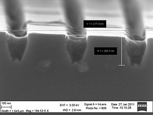
- First tests of the nanoetch recipe
-
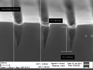 The 30 nm trenches are somewhat wider due to overexposure of E-beam resist
 -
 The 30 nm trenches are somewhat wider due to overexposure of E-beam resist


It looks like the trenches are closing up as the etch goes deeper, consistent with too much polymer deposition on the sidewall.
The options I would look at are
       1) to reduce the coil power to 700W so that the dc bias of the etch increases & you sputter more of the polymer off.
       2) increase the platen temperature to 40 C so as to reduce polymer condensation on the wafer.
       3) substitute Cl2 for some of the HBr - try a 50: 50 mix of Cl2 / HBr for the main etch with the same total gas flow.
This will reduce the amount of polymerising species in the plasma & therefore help reduce the amount of sidewall deposition. I would try these separately.
Just as a sanity check, have you got any pre-etch SEM images of the ZEP? There's a contradiction in the SEM images - in that you are seeing what looks to be undercut, whilst the trenches are also closing up. One effect is consistent with too little polymerisation whilst the other is caused by too much. The breakthrough step is actually quite a physical & directional etch, which usually doesn't cause an undercut. What exposed area do you have on the samples? link title