Specific Process Knowledge/Lithography/EBeamLithography/BEAMER: Difference between revisions
No edit summary |
|||
| (153 intermediate revisions by the same user not shown) | |||
| Line 1: | Line 1: | ||
'''Feedback to this page''': '''[mailto: | '''Feedback to this page''': '''[mailto:labadviser@nanolab.dtu.dk?Subject=Feed%20back%20from%20page%20http://labadviser.nanolab.dtu.dk/index.php/Specific_Process_Knowledge/Lithography/EBeamLithography/BEAMER click here]''' | ||
Content and illustration by Thomas Pedersen, DTU Nanolab unless otherwise noted. | |||
=Beamer guide= | |||
All users of the JEOL 9500 system must have their pattern converted to the JEOL52 V3.0 (V30) format, this conversion is done using Beamer (via the export node). Beamer can however do many other operations than this simple format conversion. Proper pattern processen in Beamer can significantly enhance the quality of the lithographical result from an EBL process. As a minimum users should become familar with PEC. In this section we will describe some of the most frequently used nodes and also provide a few node setups for specialized tasks. | |||
For a more in depth look at Beamer please refer to GenISys own [https://www.genisys-gmbh.com/in-action.html learning material found here.] | |||
Currently the content below is a mix of Beamer 6 and 7, we are working towards changing it all to Beamer 7. The difference is mostly visual though. | |||
==Beamer nodes== | |||
A quick overview of the Beamer nodes and their purpose is provided in the table below. Specific parameters of each node can be looked up in the help section of Beamer. A few of the most important nodes are described below. | |||
{| class="wikitable" | |||
|+ Important Beamer modules and methods | |||
|- | |||
! Node/module !! Short description | |||
|- | |||
| Import || Layout import | |||
|- | |||
| Export || Export to JEOL V30 and Raith GDS | |||
|- | |||
| Edit || Opens the pattern in LayoutEditor | |||
|- | |||
| Heal || Used to remove pattern overlaps | |||
|- | |||
| Transform || Used to rotate, scale or shift patterns | |||
|- | |||
| Bias || Used to grow or shrink patterns | |||
|- | |||
| AND, OR, MINUS, XOR, P-XOR, NOT || Applies a boolean operation to two inputs | |||
|- | |||
| Extract || Used to extract layers or regions of a design | |||
|- | |||
| Replace || Used to replace a cell in the design with a cell from another design | |||
|- | |||
| Merge || Merges multiple patterns into one | |||
|- | |||
| Grid || Can be used to increase layout grid and reduce geometry vertice count | |||
|- | |||
| Mapping || Used to rename layers | |||
|- | |||
| Filter || Used to select geometry based on rules, for instance by dimensions | |||
|- | |||
| Fracture || Gives the user much more control over pattern fracturing than the default export fracturing | |||
|- | |||
| ChipPlace || Graphical interface to set up arrays of patterns and assign dose to each element, excellent for dose testing | |||
|- | |||
| Visual-Job || Graphical user interface that can be used to entirely setup a job and have Beamer write the SDF and JDF files | |||
|- | |||
| PEC || Used to apply Proximity Effect Correction to a pattern by dose modulation | |||
|- | |||
| Shape-PEC || Applies PEC by both dose modulation and shape modulation, i.e. by moving pattern edges | |||
|- | |||
| 3D-PEC || Can be used for PEC of thick resist layers for gray scale lithography or PEC on multi-resist layer structures | |||
|- | |||
| Corner-PEC || PEC with emphasis on creating sharp corners | |||
|- | |||
| FDA || Feature Dose Assignment, allows assignment of doses to pattern elements, regions or entire layers | |||
|- | |||
| Rule-OPC || Used for rule based process control, for instance offset edges based on pattern dimensions | |||
|- | |||
| 2D Simulation || Used to simulate energy distribution (dose) in the resist and resulting dimensions | |||
|- | |||
| Metrology || Can be used to measure pattern dimensions, for instance to generate table of dimensions after Shape-PEC | |||
|} | |||
===Import=== | |||
The import node is used to import geometry into Beamer. While we recommend GDS for import Beamer supports the following formats: GDSII, DXF, OASIS, CIF, TXL, LEDB, PNG, STL, JEOL51, JEOL52, Raith (VB6, FRE, GPF, IWFL), NuFlare, MEBES, Micronic, NPI, HIMT and ADVANTEST. Import options differ somewhat between formats, for GDS import the options available are: | |||
''Layer Set:'' Allows import of only a selected range of layers. | |||
''Import Zero Width Paths:'' Allows polygonal paths to be imported with a defined width, i.e. convert a 1D wire to a 2D structure. | |||
''Keep Path Elements:'' If checked, polygonal paths will be perserved in addition to the 2D structure. | |||
''Import Boxes:'' Some design tools use "area boxes", a special type of geometry that is not considered a polygon. These can be converted to polygons with this option. | |||
''Ignore text, Load Text, Text as Polygon:'' Either ignores text objects, imports them as text objects or converts them to polygons. Notice that text defined in CleWin is not saved as text objects but as polygons when saving the file as GDS and hence this option is not necesarry if the design originates from CleWin. | |||
''Generic curve:'' Allows the detection of curved structures such as arcs or circles. Opens the "Approximation accuracy" field where the user can input the highest allowable deviation from the drawn polygonal structure. If curved elements are found Beamer will determine the right amount of vertices to fit the curved structure. | |||
''Keep Order of Elements:'' Preserves the order in which elements are drawn/listed in the import file. | |||
''Flatten Layout:'' Flattens the layout to one layer and one cell. | |||
{| style="border: none; border-spacing: 0; margin: 1em auto; text-align: center;" | |||
|- | |||
| [[image:BEAMER7_Import.png|400px]] | |||
|- | |||
| colspan="1" style="text-align:center;| | |||
Beamer import node. | |||
|} | |||
===Export=== | |||
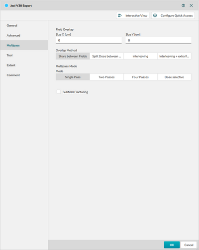
The export node will export the pattern data to the machine specific format. For exposure on JEOL 9500 export to V30. For exposure on Raith E-line export to Raith EBL File (GDS). Export to V30 has multiple options distributed on the three main panes, ''General'', ''Advanced'' and ''Multipass'', while export to Raith GDS has almost no export options. | |||
The main options on the ''General'' pane is | |||
''Machine type:'' Must be set to ''JBX-9500FS (100kV)'', notice it is not the default selection and must be set by the user. | |||
''Pattern units:'' Unit system of the pattern, should be set to 1 nm. | |||
''Shot pitch:'' Should be set to 4 units, hence 1 nm. Will be overruled by the SHOT A command in the SDF file. | |||
''Size:'' Size of the main writing field, maximum size is 1000 x 1000 µm. | |||
''Fracture mode:'' This can be used to alter the way Beamer fractures the geometry into trapezoidal shapes. The options in the export module are fairly limited, much more control can be gained by using a ''Fracture'' node. See the ''Fracture'' node for more details. | |||
''Feature Sorting in Field:'' Can be used to alter the writing order of pattern elements in each writing field. The actual result of these choices can be somewhat hard to predict. After export the result can be seen in the Viewer under ''Tool'' and either ''Show Traversal Path'' or ''Show Writing Order''. | |||
'''Important notice:''' If using the ''Fracture'' node to define the fracturing it is important in the ''Export'' node to explicitly choose not to fracture the layout during export. To ensure this select ''Cell To Field'' in the ''Field Ordering'' menu and ''NoCompaction'' in the ''Feature Sorting in Field'' of the export node. | |||
{| style="border: none; border-spacing: 0; margin: 1em auto; text-align: center;" | |||
|- | |||
| [[image:BEAMER7_Export1.png|400px]] | [[image:BEAMER7_Export2.png|400px]] | [[image:BEAMER7_Export3.png|400px]] | |||
|- | |||
| colspan="3" style="text-align:center;| | |||
JEOL V30 version of the Beamer export node. | |||
|} | |||
===Extract=== | |||
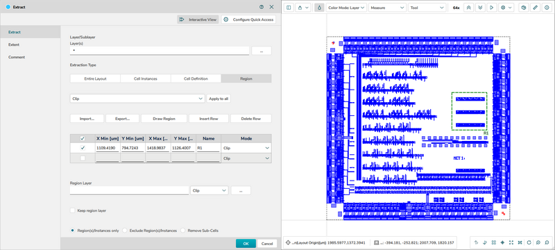
The extract node allows one to extract only parts of a design for further processing and export. This is very powerful if different parts of a pattern should be treated differently or if only part of a pattern should be exposed, for instance for dose test of the most critical features of a design. The available options are: | |||
''Layer(s):'' Extract single or multiple layers from the design file. | |||
''Extraction type:'' Allows extraction of single cells of a design or a drawn region. In the example shown below a region has been drawn in the viewer by simply Shift-left clicking to select the region. The corners of a region can also be entered nummerically. Multiple regions can be defined for extraction. By clicking the ''Exclude Region(s)/Instance'' the selected parts can be omitted from the rest of the pattern instead. | |||
''Region Layer:'' A layer of the design can be used to define regions for extraction. | |||
''Dose Classification:'' The dose modulation table (if any is present from PEC) can be truncated with the ''Shrink'' option to reflect the extracted region. | |||
{| | On the ''Extent'' pane one has the option to control the bounding box of the extracted geometry. | ||
{| style="border: none; border-spacing: 0; margin: 1em auto; text-align: center;" | |||
|- | |||
|- | | [[image:BEAMER7_Extract.png|800px]] | ||
|[[ | |- | ||
| | | colspan="1" style="text-align:center;| | ||
| | Beamer extract node. | ||
|} | |} | ||
===Fracture=== | |||
The ''Fracture'' node has changed considerably between Beamer 6 and Beamer 7. In Beamer 7 all features related to field placement has been moved into a new ''Field'' node. To gain the same functionality as in Beamer 6 simply put a ''Field'' node after the ''Fracture'' node in Beamer 7. | |||
Before pattern writing the shapes/polygons of a design must be fractured into trapezoids filled with beam/shot positions. Careful setup of how a design is fractured and shots are placed can greatly enhance the end result both in terms of critical dimension accuracy, line edge roughness and pattern stitching between writing fields. | |||
''' | {| style="border: none; border-spacing: 0; margin: 1em auto; text-align: center;" | ||
|- | |||
| [[image:BEAMER7_Fracture.png|400px]] | |||
|- | |||
| colspan="3" style="text-align:center;| | |||
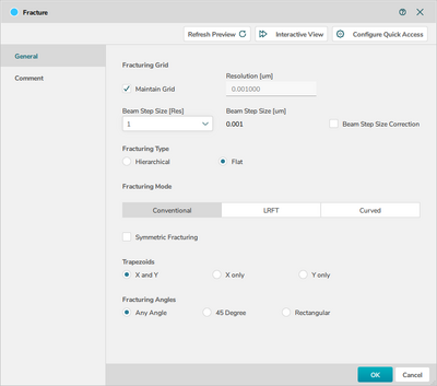
The ''Fracture'' node in Beamer. | |||
|} | |||
''' | ''Maintain grid:'' Check this to fracture at the database grid size, in most cases 1 nm. If unchecked the fracturing resolution can be changed in the ''Resolution'' field. The fracture resolutions should be set to the writing grid resolution, in most cases 1 nm. | ||
''Beam Step Size Correction:'' If checked, the program will attempt to preserve original shape outlines when beam shots are placed. | |||
''Fracturing Type:'' | |||
*''Hierarchical:'' This mode will preserve the hierarchical layout structure. | |||
*''Flat:'' This mode will remove the hierarchy in the pattern while preserving the layer information of the shapes. | |||
''Fracturing mode'' determines the method used for fracturing. | |||
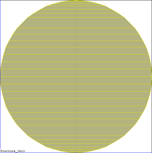
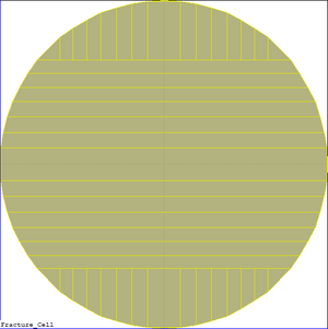
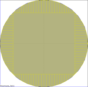
*''Conventional:'' The conventional algorithm performs mainly horizontal fractures at polygon vertices that maintain the original design intent as good as possible. This leads to many slices of trapezoids to best represent the original layout. | |||
*''Large Rectangle Fine Trapezoid:'' The LRFT algorithm attempts to minimize the number of shapes using very large rectangles for large areas and fine trapezoids for smaller features. In other words, this mode fractures the polygons with as many large rectangles as possible and completes the filling with small trapezoids. | |||
*''Curved:'' This algorithm should typically be used to fracture circles and rings. This mode allows BEAMER to shift the vertices along curves to get fractures consistent with the specified resolution and beam step size. In other words, this mode will try to detect curves in the given polygons and fracture these curves within a specified tolerance consistent with the specified resolution and beam step size. | |||
*''Symmetric Fracturing:'' This will attempt to perserve as high symmetry across the x- and y-axis as possible. | |||
{| style="border: none; border-spacing: 0; margin: 1em auto; text-align: center;" | |||
== | |- | ||
| [[image:BEAMER_Conventional.png|300px]] | [[image:BEAMER_LRFT.png|300px]] | [[image:BEAMER_Curved.png|300px]] | |||
|- | |||
| colspan="3" style="text-align:center;| | |||
Illustration of the three different fracture modes on a 400 nm diameter circle. From left to right the fracture modes are ''Conventional'', ''LRFT'' and ''Curved''. | |||
|} | |||
===Fields=== | |||
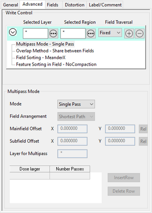
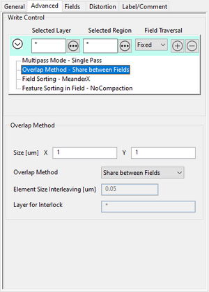
The ''Advanced'' pane allows one to divide a design into different regions and apply different fracturing methods to different regions. Simply shift-click in the layout to draw out regions. It can also be used to assign different methods by layer. Multiple setups can be added with the ''+'' button. | |||
{| style="border: none; border-spacing: 0; margin: 1em auto; text-align: center;" | |||
|- | |||
| [[image:BEAMER_A1.png|300px]] [[image:BEAMER_A2.png|300px]] [[image:BEAMER_A3.png|300px]] [[image:BEAMER_A4.png|300px]] | |||
|- | |||
| colspan="2" style="text-align:center;| | |||
Advanced pane of the ''Fracture'' node. | |||
|} | |||
''Field Traversal:'' ''Fixed'', ''Floating'' or ''Fields Follow Geometry''. The ''Fixed'' traversal will lay out main fields in a perfect grid starting from the bottom left feature of the design. The ''Floating'' field option will attempt to place geometry in the center of writing fields and is best used for sparse layouts. ''Fields Follow'' will attempt to lay out fields and their writing order such that they follow geometry. This is a good choice for waveguides and spiral structures. | |||
''Multipass Mode:'' In order to mitigate beam fluctations it is possible to divide an exposure into multiple exposures of each writing field. It is a simple averaging technique whare each pattern element is written n times, each time with 1/n of the total dose. Options are ''Single Pass'', ''Two Passes'', ''Four Passes'' and ''Dose Selective''. In the first three cases the pattern is written in either one pass (i.e. not multipass), two passes or four passes. In the dose selective approach it is possible to set the number of passes based on the dose using the table in the bottom of the window. When using multipass one must assign either a ''Mainfield Offset'', a ''Subfield Offset'' or both, such that elements are written at different placements of the writing field. | |||
''Overlap Method:'' Allows one to setup a pattern overlap between main fields to mitigate stiching problems. The overlap dimension is controlled with the ''Size'' fields. The methods available are: | |||
*''Share between fields:'' This method divides pattern elements at main field boundaries and assigns the entire dose of an element to a single writing field. An overlap region can be defined such that small elements within this overlap are placed in a single writing field to avoid stitching. | |||
*''Split Dose between Fields:'' The dose is split evenly across neighbouring fields over the designated distance. | |||
*''Interleaving:'' In this method an interleave is made between writing field boundaries over the distance set by ''Size''. The width of the interleaved strips is set in the ''Element Size Interleaving''. | |||
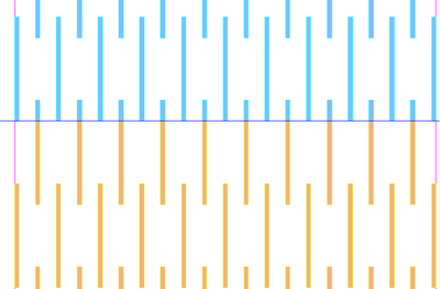
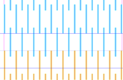
*''Interleaving + extra field:'' This method is somewhat similar to ''Interleave'' but in addition it creates an extra writing field with the interleaving part only. Thus, the interleaving part is written at 50% dose in each of the neighbouring fields and then written at 50% dose in a third (floating) writing field. | |||
{| style="border: none; border-spacing: 0; margin: 1em auto; text-align: center;" | |||
|- | |||
| [[image:BEAMER_Share2.png|400px]] [[image:BEAMER_Share1.png|400px]] | |||
|- | |||
| colspan="2" style="text-align:center;| | |||
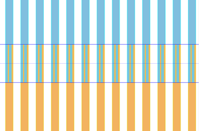
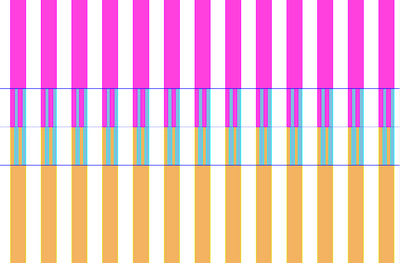
Illustration of ''Share between Fields'' overlap. On the left side the overlap distance is 0, i.e. no overlap. The rods are simply divided along the main field boundary. On the right side an overlap has been introduced such that the line of rods at the boundary is entirely placed in either of the writing fields and hence will not be stitched across two fields. | |||
|} | |||
{| style="border: none; border-spacing: 0; margin: 1em auto; text-align: center;" | |||
|- | |||
| [[image:BEAMER_Split.png|400px]] | |||
|- | |||
| colspan="2" style="text-align:center;| | |||
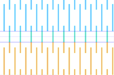
Illustration of ''Split between fields'' overlap. Over a defined distance at the writing field boundary the geometry is present in both fields but only written with half the dose, as can bee seen by the color of the overlap. | |||
|} | |||
== | {| style="border: none; border-spacing: 0; margin: 1em auto; text-align: center;" | ||
|- | |||
| [[image:BEAMER_Interleave1.png|400px]] [[image:BEAMER_Interleave2.png|400px]] | |||
|- | |||
| colspan="2" style="text-align:center;| | |||
Illustration of the ''Interleave'' overlap methods. On the left side ''Interleaving'' is used to interleave the structures at the main field boundary between the fields. On the right side "Interleaving + extra field'' is used to interleave but also add an additional writing field for the interleaved part. | |||
|} | |||
< | The ''Fields'' pane is very simple and can be used to limit the main or subfield dimensions. The maximum main field size is 1000 x 1000 µm<sup>2</sup> and the maximum subfield size is 4 x 4 µm<sup>2</sup>. | ||
'''Important notice:''' The export node will re-fracture the layout with other parameters unless one selects ''Cell To Field'' in the ''Field Ordering'' menu and ''NoCompaction'' in the ''Feature Sorting in Field'' of the export node. | |||
===ChipPlace=== | |||
A pattern can easily be set up for a dose test using the ChipPlace module. In ChipPlace one can set up a pattern to be instanced a number of time and easily assign each instance a dose. The dose can be manually set or be linearly interpolated between a start and end value for the instanced array. The output of ChipPlace is a single pattern file with all array elements assigned to individual doses (shot ranks). This also works with patterns that already have PEC applied. In that case ChipPlace will create a combined modulation of the PEC modulation and the dose test modulation. In the example below we demonstrate how to set up dose test without PEC. If PEC is needed a PEC node can simply be added before the ChipPlace node. In the example we will use the '''Array_dots''' pattern found in the examples pane. It is a simple array of dots in a 100 x 100 µm<sup>2</sup> box. The procedure is | |||
*Import a design | |||
*Add the ChipPlace node | |||
*In the '''Substrate''' tab define the substrate size. This is purely for visualization of how the pattern fits on the substrate | |||
{| style="border: none; border-spacing: 0; margin: 1em auto; text-align: center;" | |||
|- | |||
| [[image:BEAMER_1.png|800px]] | |||
|- | |||
| colspan="1" style="text-align: center;| | |||
This example uses the '''Array_dots''' pattern supplied with Beamer. Image: Thomas Pedersen. | |||
|} | |||
{| style="border: none; border-spacing: 0; margin: 1em auto; text-align: center;" | |||
|- | |||
| [[image:BEAMER_2.png|800px]] | |||
|- | |||
| colspan="1" style="text-align: center;| | |||
Choose a substrate size to visualize placement within the substrate in ChipPlace. Image: Thomas Pedersen. | |||
|} | |||
*Go to the '''Array and Data tab''' | |||
*Click '''Add Array''' | |||
*In '''Data to place''' choose '''Chip'''. It will then take the pattern connected to the ChipPlace module | |||
*Fill in array data in '''Repitition''' and '''Pitch''' to create as many dose test instance as you want. In this case we create a 10 x 2 array | |||
*Choose '''Center''' in '''Position Mode''' to have everything centered in the final output pattern (V30 file) | |||
*Click '''Assign Dose''' to open up the dose assignment page | |||
*Choose '''Dose Series''' and enter a start and end value. This is relative dose, i.e. a multiplier on the base dose defined by RESIST in the SDF file | |||
*Choose '''Raster X''' in '''Deploy Mode''' to increase dose from left to right for all rows | |||
*Click '''OK''' in both open windows to see the result | |||
This will produce a 10 x 2 array of the pattern with a relative dose from 1 to 2. Remember this dose factor is acting as a multiplier onto the base dose defined by '''RESIST''' in the SDF file. Thus if a base dose of 200 is defined by '''RESIST''' this setup will start at 200 µC/cm<sup>2</sup> and end at 400 µC/cm<sup>2</sup>. | |||
{| style="border: none; border-spacing: 0; margin: 1em auto; text-align: center;" | |||
|- | |||
| [[image:BEAMER_3.png|800px]] | |||
|- | |||
| colspan="2" style="text-align: center;| | |||
The array and dose assignment can be set up with just a few inputs. Image: Thomas Pedersen. | |||
|} | |||
{| | {| style="border: none; border-spacing: 0; margin: 1em auto; text-align: center;" | ||
|- | |||
| [[image:BEAMER_4.png|800px]] | |||
|- | |||
|- | | colspan="2" style="text-align: center;| | ||
Indicated for each element in the viewport is relative dose X and array number (x,y). Image: Thomas Pedersen. | |||
|[[ | |||
| | |||
| | |||
|} | |} | ||
To make analysis of the post exposure result easier let us add a dose label to each array element. This dose label will be exposed along with the pattern and thus when inspecting the result in SEM the (relative) dose will be visible next to the pattern. It is very easy to add: | |||
*Go to the '''Texts''' pane in the bottom window | |||
*Enter '''$DOSE_REL(3)$''' to have the relative dose printed with 3 decimals accuracy | |||
*Choose array 1 in '''Array ID''' to assign the text label to that array | |||
*Assign text labels to all array elements with the '''(*,*,2)''' command. The "2" sets the relative dose of the labels to 2 | |||
*Assign an y-axis offset of for instance -100 µm to avoid having the label printed on top of the pattern itself | |||
*Assign a decent size in the '''Size''' window, 20 µm will work for most cases | |||
*Click '''OK''' in the bottom of the window to return to the Beamer view | |||
*Run the ChipPlace node to see the result | |||
*Add an '''Export''' node and export the result as normal | |||
{| style="border: none; border-spacing: 0; margin: 1em auto; text-align: center;" | |||
|- | |||
| [[image:BEAMER_5.png|800px]] | |||
|- | |||
| colspan="1" style="text-align: center;| | |||
Final result of the ChipPlace node with relative doses from 1 to 2, ready for export to V30. Image: Thomas Pedersen. | |||
|} | |||
{| | {| style="border: none; border-spacing: 0; margin: 1em auto; text-align: center;" | ||
|- | |||
| [[image:BEAMER_6.png|800px]] | |||
|- | |- | ||
|[[ | | colspan="1" style="text-align: center;| | ||
| | Example of the added dose labels. Image: Thomas Pedersen. | ||
|- align | |||
|} | |} | ||
===Visual-Job=== | |||
Visual Job is essentially a graphical interface where one can setup a job consisting of multiple patterns. After setup Visual Job vil write the corresponding SDF and JDF files. A short video guide to [https://youtu.be/Mi_HimB0Xa8?si=7WemvXTKJMGLY2jb Visual Job is available here.] Notice that the video is from Beamer 6.2, there is only a few minor changes in Beamer 7. | |||
===PEC=== | |||
Apart from conversion to V30 the prime use of Beamer is to do Proximity Effect Correction (PEC). This is done through the PEC node. The PEC node has a quite a few options and different ways to define a Point Spread Function (PSF). The PSF is a radially symmetric function around the beam spot that defines dose received by the resist both due to the incident beam but also from scattered electrons. The PSF used in Beamer can be defined in two ways; either based on gaussian functions where the user supplies the parameters used to define the functions, or the PSF can be based on Monte Carlo simulations of electron scattering. In any case the PSF is mainly dependent on beam energy (acceleration voltage) and substrate material. The JEOL 9500 system is always used at 100 kV, the Raith eLine system can however be used at any acceleration voltage between 1 and 30 kV. The PSF changes drastically with acceleration voltage and it is very important to use a PSF generated at the correct acceleration voltage. Beamer comes with its own Monte Carlo simulator called Tracer. In Tracer one can set up a substrate material stack and simulate electron scattering at the desired acceleration voltage. The PSF can be output as a file and loaded into Beamer for PEC. | |||
==Node setups and usage examples== | |||
Latest revision as of 08:00, 14 November 2023
Feedback to this page: click here
Content and illustration by Thomas Pedersen, DTU Nanolab unless otherwise noted.
Beamer guide
All users of the JEOL 9500 system must have their pattern converted to the JEOL52 V3.0 (V30) format, this conversion is done using Beamer (via the export node). Beamer can however do many other operations than this simple format conversion. Proper pattern processen in Beamer can significantly enhance the quality of the lithographical result from an EBL process. As a minimum users should become familar with PEC. In this section we will describe some of the most frequently used nodes and also provide a few node setups for specialized tasks.
For a more in depth look at Beamer please refer to GenISys own learning material found here.
Currently the content below is a mix of Beamer 6 and 7, we are working towards changing it all to Beamer 7. The difference is mostly visual though.
Beamer nodes
A quick overview of the Beamer nodes and their purpose is provided in the table below. Specific parameters of each node can be looked up in the help section of Beamer. A few of the most important nodes are described below.
| Node/module | Short description |
|---|---|
| Import | Layout import |
| Export | Export to JEOL V30 and Raith GDS |
| Edit | Opens the pattern in LayoutEditor |
| Heal | Used to remove pattern overlaps |
| Transform | Used to rotate, scale or shift patterns |
| Bias | Used to grow or shrink patterns |
| AND, OR, MINUS, XOR, P-XOR, NOT | Applies a boolean operation to two inputs |
| Extract | Used to extract layers or regions of a design |
| Replace | Used to replace a cell in the design with a cell from another design |
| Merge | Merges multiple patterns into one |
| Grid | Can be used to increase layout grid and reduce geometry vertice count |
| Mapping | Used to rename layers |
| Filter | Used to select geometry based on rules, for instance by dimensions |
| Fracture | Gives the user much more control over pattern fracturing than the default export fracturing |
| ChipPlace | Graphical interface to set up arrays of patterns and assign dose to each element, excellent for dose testing |
| Visual-Job | Graphical user interface that can be used to entirely setup a job and have Beamer write the SDF and JDF files |
| PEC | Used to apply Proximity Effect Correction to a pattern by dose modulation |
| Shape-PEC | Applies PEC by both dose modulation and shape modulation, i.e. by moving pattern edges |
| 3D-PEC | Can be used for PEC of thick resist layers for gray scale lithography or PEC on multi-resist layer structures |
| Corner-PEC | PEC with emphasis on creating sharp corners |
| FDA | Feature Dose Assignment, allows assignment of doses to pattern elements, regions or entire layers |
| Rule-OPC | Used for rule based process control, for instance offset edges based on pattern dimensions |
| 2D Simulation | Used to simulate energy distribution (dose) in the resist and resulting dimensions |
| Metrology | Can be used to measure pattern dimensions, for instance to generate table of dimensions after Shape-PEC |
Import
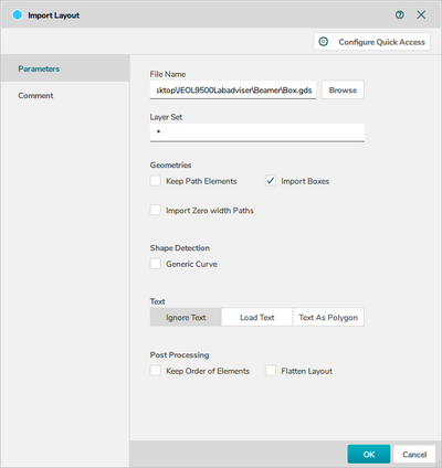
The import node is used to import geometry into Beamer. While we recommend GDS for import Beamer supports the following formats: GDSII, DXF, OASIS, CIF, TXL, LEDB, PNG, STL, JEOL51, JEOL52, Raith (VB6, FRE, GPF, IWFL), NuFlare, MEBES, Micronic, NPI, HIMT and ADVANTEST. Import options differ somewhat between formats, for GDS import the options available are:
Layer Set: Allows import of only a selected range of layers.
Import Zero Width Paths: Allows polygonal paths to be imported with a defined width, i.e. convert a 1D wire to a 2D structure.
Keep Path Elements: If checked, polygonal paths will be perserved in addition to the 2D structure.
Import Boxes: Some design tools use "area boxes", a special type of geometry that is not considered a polygon. These can be converted to polygons with this option.
Ignore text, Load Text, Text as Polygon: Either ignores text objects, imports them as text objects or converts them to polygons. Notice that text defined in CleWin is not saved as text objects but as polygons when saving the file as GDS and hence this option is not necesarry if the design originates from CleWin.
Generic curve: Allows the detection of curved structures such as arcs or circles. Opens the "Approximation accuracy" field where the user can input the highest allowable deviation from the drawn polygonal structure. If curved elements are found Beamer will determine the right amount of vertices to fit the curved structure.
Keep Order of Elements: Preserves the order in which elements are drawn/listed in the import file.
Flatten Layout: Flattens the layout to one layer and one cell.
|
|
Beamer import node. |
Export
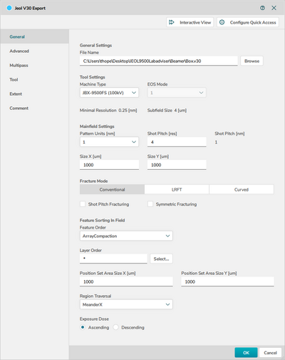
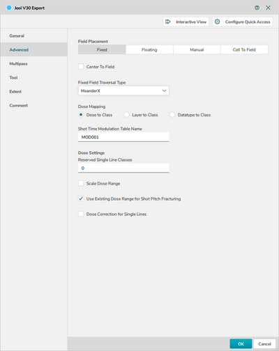
The export node will export the pattern data to the machine specific format. For exposure on JEOL 9500 export to V30. For exposure on Raith E-line export to Raith EBL File (GDS). Export to V30 has multiple options distributed on the three main panes, General, Advanced and Multipass, while export to Raith GDS has almost no export options.
The main options on the General pane is
Machine type: Must be set to JBX-9500FS (100kV), notice it is not the default selection and must be set by the user.
Pattern units: Unit system of the pattern, should be set to 1 nm.
Shot pitch: Should be set to 4 units, hence 1 nm. Will be overruled by the SHOT A command in the SDF file.
Size: Size of the main writing field, maximum size is 1000 x 1000 µm.
Fracture mode: This can be used to alter the way Beamer fractures the geometry into trapezoidal shapes. The options in the export module are fairly limited, much more control can be gained by using a Fracture node. See the Fracture node for more details.
Feature Sorting in Field: Can be used to alter the writing order of pattern elements in each writing field. The actual result of these choices can be somewhat hard to predict. After export the result can be seen in the Viewer under Tool and either Show Traversal Path or Show Writing Order.
Important notice: If using the Fracture node to define the fracturing it is important in the Export node to explicitly choose not to fracture the layout during export. To ensure this select Cell To Field in the Field Ordering menu and NoCompaction in the Feature Sorting in Field of the export node.
 | |  | | 
| ||
|
JEOL V30 version of the Beamer export node. | ||
Extract
The extract node allows one to extract only parts of a design for further processing and export. This is very powerful if different parts of a pattern should be treated differently or if only part of a pattern should be exposed, for instance for dose test of the most critical features of a design. The available options are:
Layer(s): Extract single or multiple layers from the design file.
Extraction type: Allows extraction of single cells of a design or a drawn region. In the example shown below a region has been drawn in the viewer by simply Shift-left clicking to select the region. The corners of a region can also be entered nummerically. Multiple regions can be defined for extraction. By clicking the Exclude Region(s)/Instance the selected parts can be omitted from the rest of the pattern instead.
Region Layer: A layer of the design can be used to define regions for extraction.
Dose Classification: The dose modulation table (if any is present from PEC) can be truncated with the Shrink option to reflect the extracted region.
On the Extent pane one has the option to control the bounding box of the extracted geometry.
|
|
Beamer extract node. |
Fracture
The Fracture node has changed considerably between Beamer 6 and Beamer 7. In Beamer 7 all features related to field placement has been moved into a new Field node. To gain the same functionality as in Beamer 6 simply put a Field node after the Fracture node in Beamer 7.
Before pattern writing the shapes/polygons of a design must be fractured into trapezoids filled with beam/shot positions. Careful setup of how a design is fractured and shots are placed can greatly enhance the end result both in terms of critical dimension accuracy, line edge roughness and pattern stitching between writing fields.
| ||
|
The Fracture node in Beamer. | ||
Maintain grid: Check this to fracture at the database grid size, in most cases 1 nm. If unchecked the fracturing resolution can be changed in the Resolution field. The fracture resolutions should be set to the writing grid resolution, in most cases 1 nm.
Beam Step Size Correction: If checked, the program will attempt to preserve original shape outlines when beam shots are placed.
Fracturing Type:
- Hierarchical: This mode will preserve the hierarchical layout structure.
- Flat: This mode will remove the hierarchy in the pattern while preserving the layer information of the shapes.
Fracturing mode determines the method used for fracturing.
- Conventional: The conventional algorithm performs mainly horizontal fractures at polygon vertices that maintain the original design intent as good as possible. This leads to many slices of trapezoids to best represent the original layout.
- Large Rectangle Fine Trapezoid: The LRFT algorithm attempts to minimize the number of shapes using very large rectangles for large areas and fine trapezoids for smaller features. In other words, this mode fractures the polygons with as many large rectangles as possible and completes the filling with small trapezoids.
- Curved: This algorithm should typically be used to fracture circles and rings. This mode allows BEAMER to shift the vertices along curves to get fractures consistent with the specified resolution and beam step size. In other words, this mode will try to detect curves in the given polygons and fracture these curves within a specified tolerance consistent with the specified resolution and beam step size.
- Symmetric Fracturing: This will attempt to perserve as high symmetry across the x- and y-axis as possible.
 | |  | | 
| ||
|
Illustration of the three different fracture modes on a 400 nm diameter circle. From left to right the fracture modes are Conventional, LRFT and Curved. | ||
Fields
The Advanced pane allows one to divide a design into different regions and apply different fracturing methods to different regions. Simply shift-click in the layout to draw out regions. It can also be used to assign different methods by layer. Multiple setups can be added with the + button.
  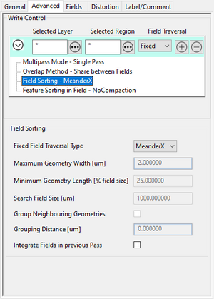 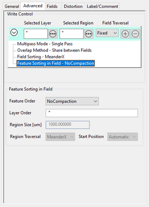
| |
|
Advanced pane of the Fracture node. | |
Field Traversal: Fixed, Floating or Fields Follow Geometry. The Fixed traversal will lay out main fields in a perfect grid starting from the bottom left feature of the design. The Floating field option will attempt to place geometry in the center of writing fields and is best used for sparse layouts. Fields Follow will attempt to lay out fields and their writing order such that they follow geometry. This is a good choice for waveguides and spiral structures.
Multipass Mode: In order to mitigate beam fluctations it is possible to divide an exposure into multiple exposures of each writing field. It is a simple averaging technique whare each pattern element is written n times, each time with 1/n of the total dose. Options are Single Pass, Two Passes, Four Passes and Dose Selective. In the first three cases the pattern is written in either one pass (i.e. not multipass), two passes or four passes. In the dose selective approach it is possible to set the number of passes based on the dose using the table in the bottom of the window. When using multipass one must assign either a Mainfield Offset, a Subfield Offset or both, such that elements are written at different placements of the writing field.
Overlap Method: Allows one to setup a pattern overlap between main fields to mitigate stiching problems. The overlap dimension is controlled with the Size fields. The methods available are:
- Share between fields: This method divides pattern elements at main field boundaries and assigns the entire dose of an element to a single writing field. An overlap region can be defined such that small elements within this overlap are placed in a single writing field to avoid stitching.
- Split Dose between Fields: The dose is split evenly across neighbouring fields over the designated distance.
- Interleaving: In this method an interleave is made between writing field boundaries over the distance set by Size. The width of the interleaved strips is set in the Element Size Interleaving.
- Interleaving + extra field: This method is somewhat similar to Interleave but in addition it creates an extra writing field with the interleaving part only. Thus, the interleaving part is written at 50% dose in each of the neighbouring fields and then written at 50% dose in a third (floating) writing field.
The Fields pane is very simple and can be used to limit the main or subfield dimensions. The maximum main field size is 1000 x 1000 µm2 and the maximum subfield size is 4 x 4 µm2.
Important notice: The export node will re-fracture the layout with other parameters unless one selects Cell To Field in the Field Ordering menu and NoCompaction in the Feature Sorting in Field of the export node.
ChipPlace
A pattern can easily be set up for a dose test using the ChipPlace module. In ChipPlace one can set up a pattern to be instanced a number of time and easily assign each instance a dose. The dose can be manually set or be linearly interpolated between a start and end value for the instanced array. The output of ChipPlace is a single pattern file with all array elements assigned to individual doses (shot ranks). This also works with patterns that already have PEC applied. In that case ChipPlace will create a combined modulation of the PEC modulation and the dose test modulation. In the example below we demonstrate how to set up dose test without PEC. If PEC is needed a PEC node can simply be added before the ChipPlace node. In the example we will use the Array_dots pattern found in the examples pane. It is a simple array of dots in a 100 x 100 µm2 box. The procedure is
- Import a design
- Add the ChipPlace node
- In the Substrate tab define the substrate size. This is purely for visualization of how the pattern fits on the substrate
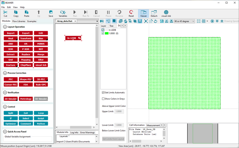
|
|
This example uses the Array_dots pattern supplied with Beamer. Image: Thomas Pedersen. |
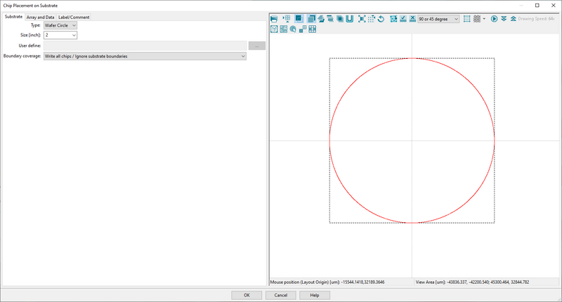
|
|
Choose a substrate size to visualize placement within the substrate in ChipPlace. Image: Thomas Pedersen. |
- Go to the Array and Data tab
- Click Add Array
- In Data to place choose Chip. It will then take the pattern connected to the ChipPlace module
- Fill in array data in Repitition and Pitch to create as many dose test instance as you want. In this case we create a 10 x 2 array
- Choose Center in Position Mode to have everything centered in the final output pattern (V30 file)
- Click Assign Dose to open up the dose assignment page
- Choose Dose Series and enter a start and end value. This is relative dose, i.e. a multiplier on the base dose defined by RESIST in the SDF file
- Choose Raster X in Deploy Mode to increase dose from left to right for all rows
- Click OK in both open windows to see the result
This will produce a 10 x 2 array of the pattern with a relative dose from 1 to 2. Remember this dose factor is acting as a multiplier onto the base dose defined by RESIST in the SDF file. Thus if a base dose of 200 is defined by RESIST this setup will start at 200 µC/cm2 and end at 400 µC/cm2.
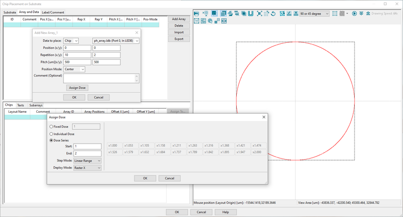
| |
|
The array and dose assignment can be set up with just a few inputs. Image: Thomas Pedersen. | |
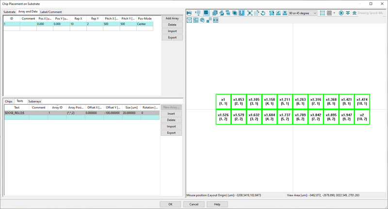
| |
|
Indicated for each element in the viewport is relative dose X and array number (x,y). Image: Thomas Pedersen. | |
To make analysis of the post exposure result easier let us add a dose label to each array element. This dose label will be exposed along with the pattern and thus when inspecting the result in SEM the (relative) dose will be visible next to the pattern. It is very easy to add:
- Go to the Texts pane in the bottom window
- Enter $DOSE_REL(3)$ to have the relative dose printed with 3 decimals accuracy
- Choose array 1 in Array ID to assign the text label to that array
- Assign text labels to all array elements with the (*,*,2) command. The "2" sets the relative dose of the labels to 2
- Assign an y-axis offset of for instance -100 µm to avoid having the label printed on top of the pattern itself
- Assign a decent size in the Size window, 20 µm will work for most cases
- Click OK in the bottom of the window to return to the Beamer view
- Run the ChipPlace node to see the result
- Add an Export node and export the result as normal
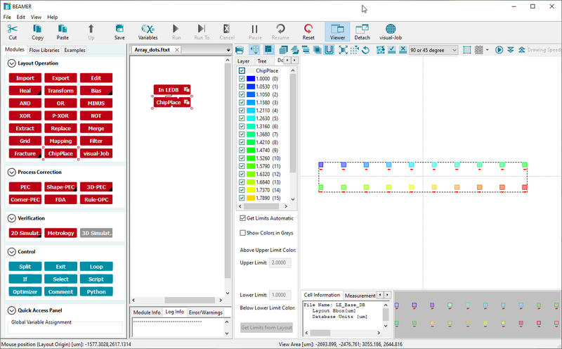
|
|
Final result of the ChipPlace node with relative doses from 1 to 2, ready for export to V30. Image: Thomas Pedersen. |
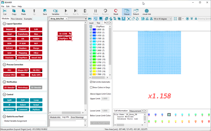
|
|
Example of the added dose labels. Image: Thomas Pedersen. |
Visual-Job
Visual Job is essentially a graphical interface where one can setup a job consisting of multiple patterns. After setup Visual Job vil write the corresponding SDF and JDF files. A short video guide to Visual Job is available here. Notice that the video is from Beamer 6.2, there is only a few minor changes in Beamer 7.
PEC
Apart from conversion to V30 the prime use of Beamer is to do Proximity Effect Correction (PEC). This is done through the PEC node. The PEC node has a quite a few options and different ways to define a Point Spread Function (PSF). The PSF is a radially symmetric function around the beam spot that defines dose received by the resist both due to the incident beam but also from scattered electrons. The PSF used in Beamer can be defined in two ways; either based on gaussian functions where the user supplies the parameters used to define the functions, or the PSF can be based on Monte Carlo simulations of electron scattering. In any case the PSF is mainly dependent on beam energy (acceleration voltage) and substrate material. The JEOL 9500 system is always used at 100 kV, the Raith eLine system can however be used at any acceleration voltage between 1 and 30 kV. The PSF changes drastically with acceleration voltage and it is very important to use a PSF generated at the correct acceleration voltage. Beamer comes with its own Monte Carlo simulator called Tracer. In Tracer one can set up a substrate material stack and simulate electron scattering at the desired acceleration voltage. The PSF can be output as a file and loaded into Beamer for PEC.

