Specific Process Knowledge/Thin film deposition/Deposition of Scandium/Sc Sputtering in Cluster Lesker PC3
Feedback to this page: click here
This page is written by Evgeniy Shkondin @DTU Nanolab if nothing else is stated.
All images and photos on this page belongs to DTU Nanolab.
The fabrication and characterization described below were conducted in 2023 by Evgeniy Shkondin, DTU Nanolab.
This page presents the results of Scandium deposition using RF Sputtering in Sputter-System Metal-Nitride (PC3) commonly known as "Cluster Lesker". The deposition target is 4" Sc (0.25" Indium bonded to Cu plate). Source #1 was used. Materials from this source can either be deposited with RF or p-DC sputtering although only RF mode has been tested so far.
The main focus of the study was the deposition rate, optical functions, and the general performance of deposition from a bigger 4” target. The scandium sputtering from the target of this size allows achieving a higher deposition rate and service to many potential applications where several hundreds of nm are needed to be put uniformly on a wafer of 150 mm or similar.
The most common application of scandium is its use as a dopant or addition to aluminum in the deposition of AlScN thin films. The presence of scandium enhances the preffered crystallographic orientation of aluminum nitride (AlN) and significantly improves the overall piezoelectric performance of the thin film. With the Cluster Lesker tool (PC3), scandium can be loaded into Source 1, while aluminum can be loaded into Source 2. Co-sputtering can then be performed from both sources, allowing for precise adjustment of individual powers, gas flows, and other parameters. This flexibility enables the tailoring of thin film stoichiometry and other properties to meet specific requirements.
4” magnetron in PC3 has more functionalities compared to the ordinary guns in cluster Lesker. It can(to some degree) moves in Z-direction. This will affect the deposition rate, uniformity and most likely play an important role in reactive sputtering. Besides that, it can be easily tilted if necessary. In this study, two Z-high positions have been compared (lowes-“home” and highest –“extended”). The effect of power has also been evaluated.
Note! It seems that Scandium is prone to oxidation, better to keep the prepared samples in a inert environment.
RF Sputtering of Scandium in Sputter-System Metal-Nitride(PC3)
The RF Sc process recipe in a Sputter-System Metal-Nitride(PC3) is following:
* Recipe Name: MD PC3_Src1 - RF_Upstream
- PC Gun Z-shift Position: Home (00.00 mm) and Extended (95.20 mm)
- Tilt: No (Target in horizontal plane)
- Deposition mode: Upstream
- Rotation speed: 10 rpm
- Pressure: 3 mTorr
- Power: 100-200 W (It is recommended to use 200W for getting high deposition rate and using "Extended" gun Z-shift position).
- Deposition time: variable
- Deposition temperature: room temperature
- Pre-sputtering time : 300s (better to give longer time to sputter away the native oxide, especially on a recently installed target)
Samples: 4" Si.
- The photography of Sc target mounted in 4” magnetron (PC3 Src1).

PC Gun Z-shift Position: Home (00.00 mm).

PC Gun Z-shift Position: Extended (95.20 mm).


Deposition Rate
- Scandium thin film deposition rate (PC3 Src1).

Scandium deposition rate as a function of power at two different PCZ-shift Gun positions.

| Scandium deposition conditions | ||||||||||||||||||||||||||||||||||||||||||||||||||||
| ||||||||||||||||||||||||||||||||||||||||||||||||||||
- PC Gun Z-shift Position: Extended (95.20 mm)
Deposition rate (nm/s) =

- PC Gun Z-shift Position: Home (00.00 mm)
Deposition rate (nm/s) =

X-ray Reflectivity (XRR)
X-ray Reflectivity analysis of Sc samples have been performed to investigate the thicknesses, roughness, and density profiles.
The scans has been obtained using Rigaku XRD SmartLab equipment. The voltage and current settings for the Cu X-ray tube were standard 40kV and 30mA. The incident optics contained a IPS (incident parallel slit) adaptor with 5 ° Soller slit. Other slits: IS=0.05mm RS1=0.05mm and RS2=0.075mm. Step size: 0.01 and measurement time - 5s for each point. Fitting procesure was performed using commercial GlobalFit software assuming the model based on Si substrate with native oxide, followed by the main Sc film with thin oxides and moisture surfaces. The results are summarized in a tables below.
- X-ray reflectivity scans of Sc thin films (PC3 Src1).

Sc thin film XRR. Power: 200W, Deposition time: 500s, Pressure 3 mTorr. PC Gun Z-shift Position: Extended (95.20 mm).

Sc thin film XRR. Power: 150W, Deposition time: 750s, Pressure 3 mTorr. PC Gun Z-shift Position: Extended (95.20 mm).

Sc thin film XRR. Power: 100W, Deposition time: 1000s, Pressure 3 mTorr. PC Gun Z-shift Position: Extended (95.20 mm).


- X-ray reflectivity scans of Sc thin films (PC3 Src1).

Sc thin film XRR. Power: 200W, Deposition time: 500s, Pressure 3 mTorr. PC Gun Z-shift Position: Home (00.00 mm).

Sc thin film XRR. Power: 150W, Deposition time: 750s, Pressure 3 mTorr. PC Gun Z-shift Position: Home (00.00 mm).

Sc thin film XRR. Power: 100W, Deposition time: 1000s, Pressure 3 mTorr. PC Gun Z-shift Position: Home (00.00 mm).


Extracted values
| XRR results for Sc thin films deposited at 3 mTorr and different powers. PC Gun Z-shift Position: Extended (95.20 mm) | |||||||||||||||||||||||||||||||||||||||||||||||||||||||||||||||||||||||||||||||||
| |||||||||||||||||||||||||||||||||||||||||||||||||||||||||||||||||||||||||||||||||

| XRR results for Sc thin films deposited at 3 mTorr and different powers. PC Gun Z-shift Position: Home (00.00 mm) | |||||||||||||||||||||||||||||||||||||||||||||||||||||||||||||||||||||||||||||||||
| |||||||||||||||||||||||||||||||||||||||||||||||||||||||||||||||||||||||||||||||||
| Fitting parameters | |||||||||||||||
|---|---|---|---|---|---|---|---|---|---|---|---|---|---|---|---|
| Sample | Moisture | ScOx | Sc | Si native oxide | Si substrate | Fitting parameters | |||||||||
| Delta | Beta | Delta | Beta | Delta | Beta | Delta | Beta | Delta | Beta | Intensity | Background | Fitting area () | R | ||
| PC Gun Z-shift Position: Extended (95.20 mm) 200W, 3mTorr, 500s | 2.6074E-6 | 6.0549E-8 | 1.1791E-5 | 2.7380E-7 | 9.6613E-6 | 8.8235E-7 | 6.5351E-6 | 1.5175E-7 | 7.5861E-6 | 1.7616E-7 | 1.18770E-000 | 1.00000E-015 | 0.4055 - 2.0000 | 0.00620 | 0.00036 |
| PC Gun Z-shift Position: Extended (95.20 mm) 150W, 3mTorr, 750s | 1.5648E-6 | 3.6281E-8 | 1.1612E-5 | 2.6923E-7 | 9.6600E-6 | 8.8099E-7 | 6.5849E-6 | 1.5267E-7 | 7.5734E-6 | 1.7559E-7 | 1.31493E-000 | 1.00000E-015 | 0.4055 - 2.0000 | 0.00966 | 0.00084 |
| PC Gun Z-shift Position: Extended (95.20 mm) 100W, 3mTorr, 1000s | 2.7829E-6 | 6.4522E-8 | 1.2191E-5 | 2.8265E-7 | 9.7208E-6 | 8.8654E-7 | 6.2206E-6 | 1.4423E-7 | 7.5734E-6 | 1.7559E-7 | 1.17570E-000 | 7.16091E-013 | 0.4055 - 2.0000 | 0.01134 | 0.00115 |
| PC Gun Z-shift Position: Home (00.00 mm) 200W, 3mTorr, 500s | 1.8998E-6 | 4.4116E-8 | 1.2471E-5 | 2.8961E-7 | 9.5349E-6 | 8.7080E-7 | 6.9494E-6 | 1.6137E-7 | 7.5860E-6 | 1.7616E-7 | 1.24263E-000 | 1.55570E-006 | 0.4055 - 3.5000 | 0.00717 | 0.00088 |
| PC Gun Z-shift Position: Home (00.00 mm) 150W, 3mTorr, 750s | 1.5348E-6 | 3.5640E-8 | 1.1663E-5 | 2.7083E-7 | 9.6088E-6 | 8.7755E-7 | 6.8450E-6 | 1.5895E-7 | 7.5860E-6 | 1.7616E-7 | 1.28094E-000 | 1.32883E-006 | 0.4055 - 3.5000 | 0.00855 | 0.00134 |
| PC Gun Z-shift Position: Home (00.00 mm) 100W, 3mTorr, 1000s | 1.2668E-6 | 2.9416E-8 | 1.2180E-5 | 2.8285E-7 | 9.5744E-6 | 8.7441E-7 | 6.7616E-6 | 1.5701E-7 | 7.5860E-6 | 1.7616E-7 | 1.29990E-000 | 1.68799E-006 | 0.4055 - 3.5000 | 0.00851 | 0.00131 |


X-ray Photoelectron Spectroscopy
X-ray Photo Electron Spectroscopy (XPS) was employed to investigate the chemical composition of deposited scandium (Sc) thin films using the XPS K-Alpha instrument. The analysis was conducted in a 'depth profile' mode, where the film was incrementally etched, and the composition was measured layer by layer. Multiple scans were performed, including survey scans and scans for specific elements like O1s, Sc2p, Sc3s and C1s, to gather comprehensive chemical information.
The Sc sample used for XPS analysis was deposited at the PC Gun Z-shift Extended position (95.20mm) under the following conditions: 200W power, 3mTorr pressure, and a deposition time of 500 seconds.
Estimated stoichiometry is following: Sc=55.51%, O=36.49%, C=8%.
The Sc target used in the experiment was new, and due to its susceptibility to oxidation, there is a possibility of a pronounced level of Scandium oxynitride formation. We believe that more extensive usage of the target will remove the oxidized top layer. Additionally, it is necessary to perform preconditioning (pre-sputtering) of the target before using it in applications. This pre-sputtering process will help minimize the oxygen level in the resulting film.
- X-ray Photoelectron Spectroscopy of Sc thin films (PC3 Src1).

Survey spectrum of Sc thin film. The films has been etched for 580s wiht Ar+ ions at low current and 1000eV energy.

- X-ray Photoelectron Spectroscopy of Sc thin films (PC3 Src1). High resolution scans during the Ar ion etch (depth-profiles).

Sc 2p signal. 30 levels in total. 20s of etch with Ar+ ions at low current and 1000eV energy between the measurements.

Sc 3s signal. 30 levels in total. 20s of etch with Ar+ ions at low current and 1000eV energy between the measurements.

O 1s signal. 30 levels in total. 20s of etch with Ar+ ions at low current and 1000eV energy between the measurements.

C 1s signal. 30 levels in total. 20s of etch with Ar+ ions at low current and 1000eV energy between the measurements.


- X-ray Photoelectron Spectroscopy of Sc thin films (PC3 Src1). 2-Dimensional depth profiles.
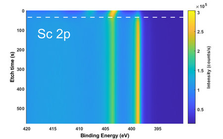
2D profile of Sc 2p signal. 30 levels in total. 20s of etch with Ar+ ions at low current and 1000eV energy between the measurements.

2D profile of Sc 3s signal. 30 levels in total. 20s of etch with Ar+ ions at low current and 1000eV energy between the measurements.

2D profile of O 1s signal. 30 levels in total. 20s of etch with Ar+ ions at low current and 1000eV energy between the measurements.

2D profile of C 1s signal. 30 levels in total. 20s of etch with Ar+ ions at low current and 1000eV energy between the measurements.


- X-ray Photoelectron Spectroscopy of Sc thin films (PC3 Src1). High resolution scans fitted with Lorentz-Gaussian functions.

Sc 2p signal with fitted functions. Less useful for stoichiometry calculation, due to the profile complexity. The film has been etched for 160s with Ar+ ions at low current and 1000eV energy before the scan.

Sc 3p signal with fitted functions. Better for stoichiometry calculation, due to the profile simplicity. The film has been etched for 160s with Ar+ ions at low current and 1000eV energy before the scan.

O 1s signal with fitted functions. The film has been etched for 160s with Ar+ ions at low current and 1000eV energy before the scan.
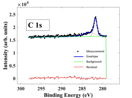
C 1s signal with fitted functions. The film has been etched for 160s with Ar+ ions at low current and 1000eV energy before the scan.


