Specific Process Knowledge/Thermal Process/Resist Pyrolysis Furnace: Difference between revisions
No edit summary |
No edit summary |
||
| Line 28: | Line 28: | ||
!colspan="2" border="none" style="background:silver; color:black;" align="center"|Equipment | !colspan="2" border="none" style="background:silver; color:black;" align="center"|Equipment | ||
|style="background:WhiteSmoke; color:black"|<b> | |style="background:WhiteSmoke; color:black"|<b>ATV</b> | ||
|- | |- | ||
!style="background:silver; color:black;" align="center"|Purpose | !style="background:silver; color:black;" align="center"|Purpose | ||
| Line 35: | Line 35: | ||
*Pyrolysis of different resist layers to form conductive structures | *Pyrolysis of different resist layers to form conductive structures | ||
|- | |- | ||
!style="background:silver; color:black" align="center" valign="center" rowspan=" | !style="background:silver; color:black" align="center" valign="center" rowspan="3"|Process parameter range | ||
|style="background:LightGrey; color:black"|Temperature | |style="background:LightGrey; color:black"|Temperature | ||
|style="background:WhiteSmoke; color:black"| | |style="background:WhiteSmoke; color:black"| | ||
*0- | *0-1100 <sup>o</sup>C | ||
*Temperature ramp-up rate: Max 10 <sup>o</sup>C/min | *Temperature ramp-up rate: Max 10 <sup>o</sup>C/min | ||
*Temperature ramp-down rate: Relative slow (depending on the furnace temperature) | *Temperature ramp-down rate: Relative slow (depending on the furnace temperature) | ||
|- | |||
|style="background:LightGrey; color:black"|Vacuum | |||
|style="background:WhiteSmoke; color:black"| | |||
*Yes, but using N2 and O2 process gasses | |||
|- | |- | ||
|style="background:LightGrey; color:black"|Nitrogen flows | |style="background:LightGrey; color:black"|Nitrogen flows | ||
| Line 50: | Line 54: | ||
|style="background:LightGrey; color:black"|Batch size | |style="background:LightGrey; color:black"|Batch size | ||
|style="background:WhiteSmoke; color:black"| | |style="background:WhiteSmoke; color:black"| | ||
*One-25 50 mm wafers (placed on a Si support wafers) | |||
*One- | *One-25 100 mm wafers | ||
*One- | *On2-25 150 mm wafers | ||
*Several smaller samples if these are placed on a support wafer | |||
|- | |- | ||
| style="background:LightGrey; color:black"|Allowed materials | | style="background:LightGrey; color:black"|Allowed materials | ||
Revision as of 13:17, 11 May 2015
Feedback to this page: click here
Resist Pyrolysis Furnace
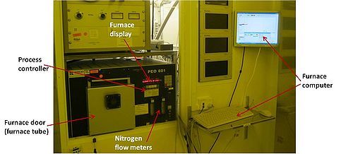
The Resist Pyrolysis Furnace is used for resist pyrolysis, where samples with different resist layers are heated up to maximum 1000 oC in a nitrogen atmosphere. At high temperatures carbon is formed by pyrolysis of the resist. In this way conductive structures can be made from a resist patterned sample.
If oxygen from the air or from outgassing of the resist is present in the furnace, the resist layer will be removed. Thus, for each process it is important to include a step with a high nitrogen flow at a lower temperature, before a high temperature for resist pyrolysis is obtained. Pyrolysis of a large amount of resist may also be a problem due to resist outgassing.
During processing the furnace is rapidly heated by use of six long heating lamps situated around the furnace tube, and cooling is done (rather slowly) by use of cooling fans. The furnace is purged with a controlable nitrogen flow. There is no vacuum on the furnace.
The user manual, user APV and contact information can be found in LabManager:
Process information
There are no standard processes on the furnace.
| Equipment | ATV | |
|---|---|---|
| Purpose |
| |
| Process parameter range | Temperature |
|
| Vacuum |
| |
| Nitrogen flows |
| |
| Substrates | Batch size |
|
| Allowed materials |
| |
