Specific Process Knowledge/Etch/OES
Unless otherwise stated, the content of this page was created by the dry etch group at DTU Nanolab
Optical endpoint detection on the dry etch tools at DTU Nanolab
Several dry etch tools at DTU Nanolab are equipped with an endpoint detection system. Out of those systems only one is not of the type optical endpoint detection. The instruments are:
- ICP Metal Etch
- III-V ICP
- Pegasus 1
- Pegasus 2
- Pegasus 4
The section below describes the principle behind the optical endpoint detection system.
Optical Emission Spectroscopy as endpoint detection
The etch process:
As an example, let's take the etching of silicon by fluorine in one of the dry etchers. The fluorine is supplied to the system by a carrier gas, in this case as SF6, that is fed to the process chamber using mass flow controllers. Driven by the RF generators (both coil and platen) the plasma will decompose the gas in a series of dissociation and ionisation reactions to form fluorine radicals F*. In the areas on the wafer that are not covered by a mask, the exposed silicon atoms will be attacked aggressively by the fluorine radical to form volatile SiF. As such, the SiF will desorp from the wafer surface and eventually get pumped away.
The plasma:
Inside the process chamber, the RF field will ionize the gas molecules to form ions, radicals and electrons. Much lighter and hence more mobile, the fast moving electrons collide with the gas constituents pushing the latter into excited states from which they may decay under emission of photons. This is what makes the plasma glow as these photons typically have an energy in the visible range. As each component in the plasma has a unique set of allowed excited states one can extract the information about composition of the plasma by analyzing the light coming out of it.
The OES hardware:
The light emitted from the plasma is collected through a view port in the process chamber - preferably directly facing the plasma itself above the wafer. A lens is mounted to focus the light onto an optical fiber feeding it to a spectrometer. The Verity spectrograph and SD1024 controller with SpectraView software are installed on the tools in the list above. It has a 200 nm to 800 nm range with a 0.5 nm step enabling the simultaneous monitoring of any number of narrow bandwidths as a function of time.
Example: The etching of silicon by fluorine:
The table below contains the most important emission lines for some of the species in dry etching.
| Monitored species | Wavelength (nm) | Monitored species | Wavelength (nm) | |
| Al | 308.2, 309.3, 396.1 | In | 325.6 | |
| AlCl | 261.4 | N | 674.0 | |
| As | 235.0 | N2 | 315.9, 337.1 | |
| C2 | 516.5 | NO | 247.9, 288.5, 289.3, 303.5, 304.3, 319.8, 320.7, 337.7, 338.6 | |
| CF2 | 251.9 | O | 777.2, 844.7 | |
| Cl | 741.4 | OH | 281.1, 306.4, 308.9 | |
| CN | 289.8, 304.2, 387.0 | S | 469.5 | |
| CO | 292.5, 302.8, 313.8, 325.3, 482.5, 483.5, 519.8 | Si | 288.2 | |
| F | 703.7, 712.8 | SiCl | 287.1 | |
| Ga | 417.2 | SiF | 440.1, 777.0 | |
| H | 486.1, 656.5 |
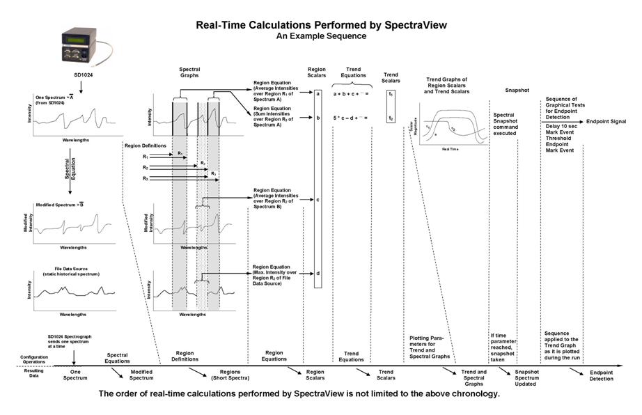
SpectraView:
At the center of the SpectraView software is the configuration file (*.svc file) that dictates what to be done.
Below is a figure
Process considerations
The intensity of the light:
The intensity of the light will depend on whether the molecule is a reactant or an etch product:
- Reactant: The concentration in the plasma:
- The carrier gas flow rate
- The RF power (both coil and platen)
- The process pressure
- Etch product:

