Specific Process Knowledge/Thin film deposition/Temescal/Good to know about the Temescal
Feedback to this page: click here
All contents on this page by DTU Nanolab staff.
Temescal processing
Good-to-know information about how the Temescal e-beam evaporator works:
Deposition rate and thickness measurement accuracy
The machine measures the thickness of the growing film with a Quartz Crystal Microbalance or QCM. The machine calls it the Xtal (crystal). This is a very thin piece of quartz that resonates at about 5-6 MHz when a voltage is applied across it. The resonance frequency varies with the mass of the crystal, and when material is deposited on one side of it, the frequency changes. This is measured by the crystal monitor, which can then calculate the deposited thickness. See image.

The thickness calculation depends on the material density as well as other physical factors. A tooling factor is used to adjust the calculation based on the geometry of the setup, since the crystal is not in the same place as the wafers so the thickness deposited on the crystal is lower than on the samples. The tooling factor will also more or less correct for the difference in density of the thin film compared to the bulk material density used in the calculation.
The tooling factor is calibrated for a particular deposition rate. It may not be perfectly accurate for other deposition rates, but should easily be within the 10 % accuracy that we test for in our quality control measurements. For very thin films < 20 nm the thickness measurement will be less accurate than for thicker films.
The machine gives a rough number for the crystal lifetime simply based on how thick a layer it calculates has been deposited on it. If many layers have been deposited and there is stress in the layers (e.g., in Cr or Ni), there may be partial delamination, which can make the thickness measurement inaccurate. In this case the lifetime estimate given by the machine will be inaccurate. If you think the crystal is not measuring correctly, please let us know. We exchange the crystals usually around 20 % lifetime use.
Heating during the deposition
If the material you are depositing requires a lot of heat to evaporate, the substrates may get warm during the deposition.
A temperature test of a 100 nm Al deposition at 10 Å/s showed that the back of the wafer stays below 37 oC. The same is true for 10 nm Ti plus 90 nm Au at 10 Å/s. In contrast, deposition of 100 nm Nb at 2 Å/s heated the substrate to above 104 oC (but the back of the wafer stayed at less than 110 oC). Deposition of 60 nm W at about 1 Å/s heated the substrate to more than 123 oC.
You may get some idea of how much the substrate will be heated by looking at the temperature required to give a reasonable vapor pressure for the evaporation. You can find some of Honig's vapor pressure curves in this online handbook section about e-beam evaporation.
Please contact us if you would like to test the heating of the substrates (write to thinfilm@nanolab.dtu.dk).
The e-beam and the Cu hearth


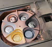
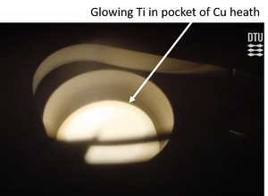
The e-beam deposition takes place from a metal target that is located in a water-cooled copper hearth. We have 6 pockets available in the E-beam evaporator (Temescal) and the Wordentec. When in use, a lid covers the 5 pockets that are not being heated. Often the metal is placed directly in the pocket in contact with the copper, while in some cases a liner is used to insulate the material from the liner. For instance in the image on the left you see that Cu for evaporation is placed in a liner so it does not simply fuse with the hearth. A liner can also be used to reduce the heat dissipation from the material.
At the start of the deposition and for every 100 nm, please check that the e-beam hits the target material rather than the hearth next to the pocket or the bottom of the pocket.
1) Check that the e-beam sweep has not shifted away from the material onto the hearth. This could happen if the filament assembly has been distorted by heat for example.
2) Check that there is enough material in the pocket, so that the beam does not hit the bottom of the pocket. If you burn a hole in the bottom of the pocket, cooling water can leak into the chamber and it may flood!
