Specific Process Knowledge/Lithography/EBeamLithography/RaithElphyManual
Feedback to this page: click here
Purpose, location and technical specifications
The Raith Elphy system is a pattern generator built onto the LEO Scanning Electron Microscope (SEM) in cleanroom F-2. All users must therefore acquire license to use the SEM LEO before acquiring license to the Raith Elphy system.
Techical Specification
The system can be characterized as follows:
- Electron-beam scanning speeds, f, up to X MHz are available (which is maximum scan speed).
- The acceleration voltage is maximum 25 kV.
- The maximum field-size without stitching is X µm x Y µm.
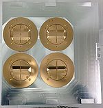
- The machine has a chip holder that fits to 2 - 3 chips with sizes of approximately 1 x 1 cm2 each. A larger chip or wafer can also be mounted on a holder without a Faraday's cup.
Mounting of chips or wafers into chamber
It can be difficult to align the beam properly to a chip coated with e-beam resist. It is thus recommended to remove the resist on a corner of the chip, preferably a place on the chip where you easily can adjust the beam, i.e. on metallised structures on the chip.
- Ventilate the SEM chamber
- Mount your chips(s) on the Raith Specimen holder
- Mount the holder on the SEM stage, evacuate the SEM chamber
Software login
- Start the Raith ELPHY Quantum software from the desktop of the Raith computer (screen to the right).
- Login with the following password:
User ID          administrator
Password         Renrum12
- Start RemCon32 from the desktop on the SEM computer (screen to the left), choose 'COM 6', right-click and press 'start'
Pepare beam for writing
Before you start preparing your beam, a few recommendations:
- It is recommended to move the stage (by joystick) instead of deflecting the beam (ctrl + tab); this to ensure that you work with an undeflected beam while preparing the beam for patterning and while patterning your GDS.
- It is recommended not to rotate the scan by the 'scan' knob; this...
Prepare beam
- Measure beam current:
- Click 'Stage Control/Positions/Faraday's cup', make sure the stage moves to the center of the Faraday's cup, increase the magnification to 100.000x or more
- Toggle beam blanker to switch on beam
- Make sure you operate at a working distance of 5 mm
- Click 'XX' to measure beam current
- Move the stage to a corner of your chip. With the joystick (or from the 'stage' tab in the SEM software), rotate the stage to align the chip
- Adjust beam quality, i.e. focus, astigmatism, wobbling at a magnification of 100.000 x or more
- Move to a new spot on the chip and switch the SEM to 'spot mode'; burn a spot in the resist (approximately 20s). Correct astigmatism and aperture alignment on that spot.
- Burn a spot with a larger magnification and adjust beam quality again.
- Burn a spot at a lower magnification to see that the spot is circular at this magnification
Stage adjustment
XY is stage coordinate system, UV is sample coordinate system:
- Origin correction:
- Click 'Adjustment/Adjust UV/Origin correction'
- Move the stage to the lower left corner of the chip
- Enter (U,V)=(0,0) and click 'adjust'
- Angle correction:
- Click 'Adjustment/Adjust UV/Angle Correction', make sure the system is in 'Global' mode
- Turn on the crosshair (SmartSEM/View)
- Set magnification to approximately 100x
- turn off beam and click 'Label1/flash'-icon to move stage to the origin.
- Click 'label1/pippette'-icon
- Move stage to the lower right corner of the chip
- click 'label2/pipette'-icon.
- Click adjust: the button hereafter turns green

