LabAdviser/314/Microscopy 314-307/TEM/ETEM/OneView
Feedback to this page: click here
(content by Jens Kling @DTU Nanolab, September 2021)
Gatan OneView camera and GMS3
Here are a few information on the OneView camera and the control in GMS3:
General info
- CMOS camera with 4096 x 4096px (pixel size: 15µm) --> 61.4 x 61.4mm sensor size; conversion efficiency @300kV: 26.42 ADC counts/Prim e- (our camera)
- Imaging mode: 25fps for full 4k x 4k resolution (single frame exposure time: 0.04s); 100fps @ 2k x 2k; 200fps @ 1k x 1k; 300fps @ 512 x 512
- Diffraction mode: about 7fps for full 4k x 4k (single frame exposure time: 0.16s)
- drift correction available
- In in situ mode: look back option available up to 30s
- In our setup, the OneView camera exclusively uses the pre-specimen shutter in idle state (beam on the camera but camera not running), which means the sample is not illuminated.
Possible Issue
We came across a strange behavior in GMS3 when acquiring images with drift correction on the OneView camera. We are specifically talking about the acquisition in general imaging mode. When the drift correction is used, GMS allows to "trim" the acquired image after drift correction to the area where all frames have information. This leads to smaller images than the general 4096x4096px and also uneven number of pixels in x- and y-direction. So far so good.
Now it appears that when the trimming option is used, even though the images might have different number of pixels in x- and y-direction (and we are typically talking about maybe up to 20-30px), the software adjusts the lengths of the image to be square (f.ex. 73nmx73nm). This causes the pixel calibration in both directions, x and y, to be slightly different, which means, when you measure length in different directions, they differ.
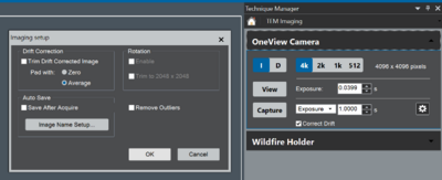
You can avoid this by NOT using the trim function with the drift correction. Use the gear icon in the acquisition control panel in GMS and un-select the trim function.
If you already have images that show this special "feature", you can try to re-calibrate your image afterwards. In the tags of the image you can find the actual magnification (not the indicated magnification). The pixel size on the camera is 15µm. Dividing the pixel size by the magnification gives you the length per pixel.
We will bring this issue forward to Gatan but I don't expect any fast response/reaction. My strong suggestion would be, acquire without trimming!
Operation
1. If the computer for the OneView camera is not running (large screen), start the computer. It is located in the technical room behind the microscope (large computer with a lot of hard drive slots). The login can be found on the whiteboard.
2. If GMS3 (Gatan Microscopy Suite; also known as Digital Micrograph) is not running yet, click on the GMS icon and acknowledge any information message (elevated privileges; using potentially harmful plug-ins).
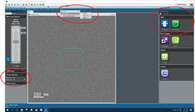
3. Check in the Camera Monitor that the temperature is -5°C. Else, wait until it reaches this temperature.
4. On the Microscope PC, the software Gatan Remote should be running in the background. If not, start this software.
5. Make sure you are an Power User. Click on Help in the top task bar and select Power User under User Mode. Now you have all relevant settings and properties available.
6. On the left hand side under Microscope, GMS shows the visualization of the TEM. Here, HT and Magnification should be the same as in the Microscope PC. Clicking on Valves will open or close the Column Valves, Blank will blank the beam before the sample, clicking on the Phosphorous screen will lift or lower the screen. Right click on the OneView camera icon opens a context menu, where the camera can be inserted or retracted.
!!! The Ultrascan camera needs to be retracted before inserting the OneView camera !!!
7. On the frontpage right hand side, you find the Technique Manager. Under TEM you find TEM imaging and In-situ imaging.
Image acquisition
1. Choose TEM imaging under Technique Manager for general image acquisition.
2. Options:
- I for imaging mode, D for diffraction mode; binning from 4096px down to 512px (when changing mode/binning, wait a minute for the electronics to stabilize again)
- Live and Capture to follow the sample on the camera and acquire individual images.
- The cogwheel icon opens additional options like auto save and how drift corrected images are handled.
- Correct Drift is the drift correction between individual frame acquisition. It adds a cyan window to the Live View window, which can be moved. Drift correction is based on this section of the image.
Imaging mode
- The camera is running on the maximum frame rate (minimum exposure time) for the selected binning. For 4k it means, each individual frame is acquired at about 0.04s (25fps).
- Changing the Exposure (no matter if in View of Capture mode) means, the camera acquires individual frames with the shortest possible exposure time, and sums them up until the selected exposure time is reached. So, it's not the "real" exposure time on the camera which is changed, but the number of individual frames in the summed image.
- Correct Drift aligns this stack of individual frames.
- This means the signal-to-noise in each individual frame should be high enough to get a decent summed final image.
- There is an additional feature which can help with low-dose image capture: When changing "Exposure" next to Capture into "Low dose", it is possible to set a dose rate. Then the camera will expose the camera chip until this dose rate on the image is achieved. In that case, the "real" exposure time is changed, which can help with low intensity on the camera. You should make sure that the dose calibration is set properly (Set dose calibration for OneView).
Diffraction mode
- In diffraction mode, the minimum exposure time increase 4 times. For 4k this means to 0.16s.
- Increasing the exposure results in summing individual frames (as in imaging mode).
- As the minimum exposure time for the individual frame is 4x higher, the signal-to-noise in the individual frame is better compared to imaging mode. This can help for very low dose acquisition.
In Situ Imaging
1. Choose In Situ Imaging under Technique Manager for in situ image acquisition.
2. Options:
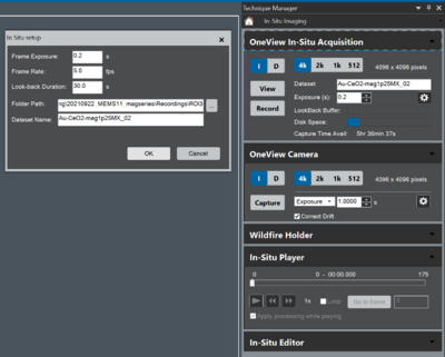
- Under In-Situ Acquisition there are the same options as in Image Acquisition for I, D and different binning.
- The cogwheel icon opens the options for:
- Frame Exposure/Frame Rate (they are linked together)
- Look-back Duration
- Folder Path to save the dataset
- Dataset Name
- Frame Exposure/Frame Rate (they are linked together)
- Look-back can be up to 30s. This means, when starting View the LookBack Buffer will fill up (indicated by the blue bar on the control panel). When clicking on Record the time in the LookBack Buffer will be added in front of the dataset. F.ex. when LookBack is 30s and the buffer is completely filled, the immediate 30s before clicking on Record will be added in front of the dataset.
- Exposure in In-Situ Acquisitions means "real" exposure time on the camera.
- Each frame will be saved hierarchically in the folder under Hour_xx, Minute_xx, Second_xx.
Additional information


