LabAdviser/314/Microscopy 314-307/Technique/Holo/Off-axis ETEM: Difference between revisions
No edit summary |
|||
| Line 1: | Line 1: | ||
'''Feedback to this page''': '''[mailto:labadviser@nanolab.dtu.dk?Subject=Feed%20back%20from%20page%20http://labadviser.nanolab.dtu.dk/index.php/LabAdviser/314/Microscopy_314-307/Technique/Holo/Off-axis_ETEM click here]''' | '''Feedback to this page''': '''[mailto:labadviser@nanolab.dtu.dk?Subject=Feed%20back%20from%20page%20http://labadviser.nanolab.dtu.dk/index.php/LabAdviser/314/Microscopy_314-307/Technique/Holo/Off-axis_ETEM click here]''' | ||
<span style="background:#FF2800">THIS PAGE IS UNDER CONSTRUCTION</span>[[image:Under_construction.png|200px]] | |||
(''content by Mads Søndergaard Larsen @DTU Nanolab, May 2024'') | (''content by Mads Søndergaard Larsen @DTU Nanolab, May 2024'') | ||
Revision as of 17:41, 6 May 2024
Feedback to this page: click here
THIS PAGE IS UNDER CONSTRUCTION
(content by Mads Søndergaard Larsen @DTU Nanolab, May 2024)
Electron Holography on the ETEM
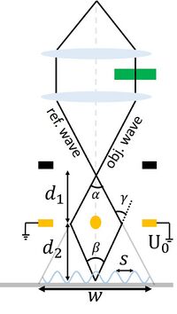
Off-axis electron holography is a transmission electron microscopy technique that is sensitive to the phase of the electrons passing through the specimen. The measurement of phase changes of electrons is very important for measuring material properties like mean inner potential and built-in potential. It is also very important in measuring charge distribution across specimens at a high spatial resolution. In this technique a part of the electron beam passes through the specimen and the other part passes through vacuum. A biprism wire (see the below figure) in the plane of the SAD apertures is held at a fixed potential and this creates an interference pattern between the electrons passing through the specimen (object wave) and vacuum/support (reference wave). The biprism can be put anywhere in the imaging system, however it is easiest to have it in the SAD plane due to the apertures being retractable and modified. The most important thing for holography is where the first intermediate image is formed, which needs to be out of plane from the biprism in order for the waves to produce the interference pattern (see https://doi.org/10.1016/0304-3991(96)00017-4). In order to remove effects from the TEM or other instabilities, reference holograms are usually acquired right after the object holograms. They are later used for reconstruction.
The detailed procedure for obtaining electron holograms is described below. The procedure has been used for obtaining holograms of in liquid phase transmission electron microscopy or of single features on a C-grid. Some tips are also shown at the end of the document.
Procedure for Performing Electron Holography in ETEM
Setting up the ETEM for Holography
- Fill Liquid nitrogen in the dewar twice or thrice -once at the beginning of the session prior to inserting the TEM holder, once after 30 minutes into the session, and the once around half time of the full-day session.
- Switch on the power supply at the backside of the room (the display will show 0V and 0A when turned on)
- Switch on the control box (under the microscope PC) (ensure the polarity is at +V, -V would diverge the reference and object wave)
- Switch cables on SAD from the wire saying “Ground” to the wire saying “Power”
- Insert your holder. First reset the holder such that the compustage is at x,y,z = 0,0,0, and both α and β tilt is at zero degrees. The insertion of the holder is similar to normal, by first parking the holder in the air-lock vent cycle (10min). Afterwards, rotate the holder to 12 o’clock and insert the holder slowly (the vacuum from the column will slowly pull it in)
- Find the specimen and ensure the beam is centered (Beam Alignment)
- If needed (alignment is way off): Load the appropriate TEM alignment, e.g. 300 kV TEM. This is done by going to Alignment tab → Alignment → Flapout → load the alignment file for the correct keV, e.g. Main_300kV. Select one particular alignment and the press Ctrl+A for selecting all and then move them from “Available” to “Selected” by clicking on the Apply button.
- If needed: Load the FEG register for TEM for the electron energy chosen in step 5 above. This is done by going to Gun tab → FEG Register → Choose the correct register → Click on Set
- Make sure that the size of C2 aperture is set to 150 µm. Go to Mono tab → Aperture → C2 → adjust and play with multifunctional knobs MFx and MFy on the left and right control panels for centering the chosen C2 aperture.
- lower C2 aperture can be used, however some of the beam is not passed through and can have an impact on the holograms.
- Adjust the monochromator so that is does not interfere with the image
- Translational alignment of the monochromator: Go to the Monochromator panel → click on shift and play with MFx and MFy to center the monochromator around the beam
- Strength of the monochromator: While in the monochromator panel, unclick the shift (yellow to grey) and click the focus button. Adjust the strength of the monochromator with the intensity (Mono = -30 → -40 is usually the range).
- The dose can further be reduced at lower Mono values, e.g. -100 or lower (adjust for different samples, however you need enough electrons to obtain good holograms. Test this when reconstructing if needed)
- Insert the OneView (CMOS) camera. Make sure the BM-Ultrascan is retracted. Go to the Oneview PC → Microscope Display → Click the Camera Icon → “Insert”.
- Open the display of the camera: Click TEM Imaging/Holography → “View”
- Depending on the resolution, two different routes are needed. For medium resolution, I advice using Lorentz mode, which uses a weaker Lorentz lens and switches off the twin-pole object lens. For high-resolution, use the conventional HR-TEM mode.
